Associate
June 18, 2026
Question

STM32F722RET6 timeout at USB_CoreReset() with USB3300EZK

  • June 18, 2026
  • 7 replies
  • 137 views

Environment & hardware:

STM32F722RET6:LQFP64

USB3300EZK

STM32CubeIDE v2.1.1

STM32CubeMX v6.17.0

Windows 11 OS


Description of problem:

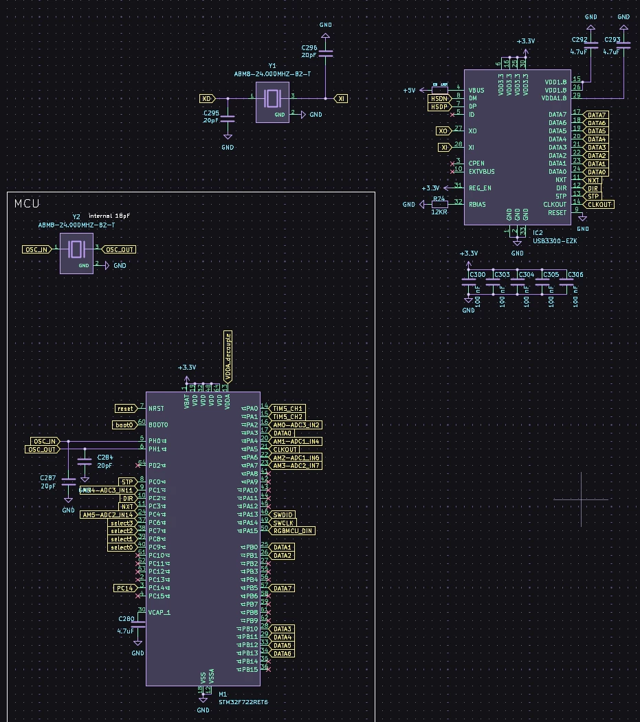
I am trying to use ULPI with external HS USB phy with the follwing schematic:

when calling MX_USB_DEVICE_Init(), it will be stuck at 

 /* Required few clock cycles before accessing USB PHY Controller Registers */
for (volatile uint32_t i = 0; i < 10; i++) {
__NOP(); // No Operation instruction to create a delay
}

/* Core Soft Reset */
USBx->GRSTCTL |= USB_OTG_GRSTCTL_CSRST;

do
{
count++;

if (count > HAL_USB_TIMEOUT)
{
return HAL_TIMEOUT;
}
} while ((USBx->GRSTCTL & USB_OTG_GRSTCTL_CSRST) == USB_OTG_GRSTCTL_CSRST);

return HAL_OK;
}

in USB_CoreReset(), eventually returning HAL_TIMEOUT.


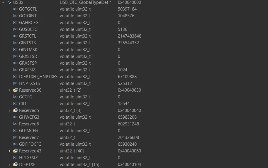
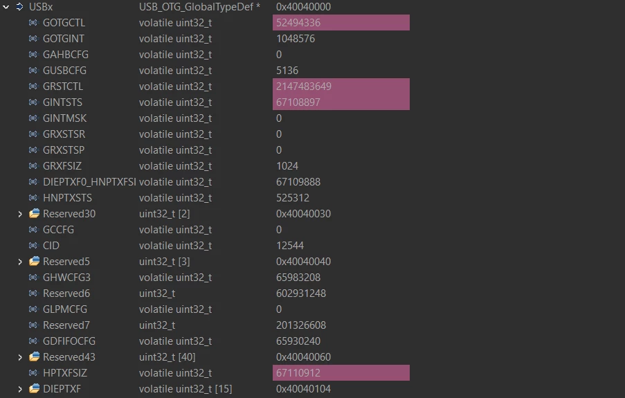
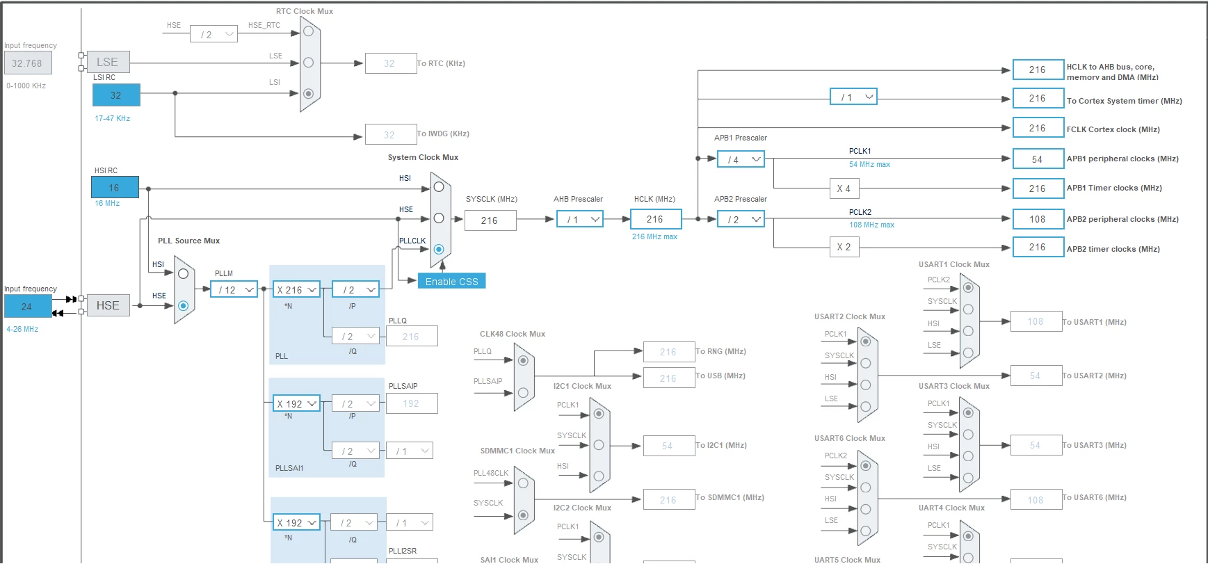
Images of USBx and RCC:

USBx before core soft reset
USBx after soft core reset
RCC before & after soft core reset

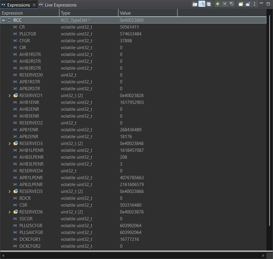
My clock configuration, everything not included in this image is greyed out

ULPI pins:

 /**USB_OTG_HS GPIO Configuration
PC0 ------> USB_OTG_HS_ULPI_STP
PC2 ------> USB_OTG_HS_ULPI_DIR
PC3 ------> USB_OTG_HS_ULPI_NXT
PA3 ------> USB_OTG_HS_ULPI_D0
PA5 ------> USB_OTG_HS_ULPI_CK
PB0 ------> USB_OTG_HS_ULPI_D1
PB1 ------> USB_OTG_HS_ULPI_D2
PB10 ------> USB_OTG_HS_ULPI_D3
PB11 ------> USB_OTG_HS_ULPI_D4
PB12 ------> USB_OTG_HS_ULPI_D5
PB13 ------> USB_OTG_HS_ULPI_D6
PB5 ------> USB_OTG_HS_ULPI_D7
*/
GPIO_InitStruct.Pin = GPIO_PIN_0|GPIO_PIN_2|GPIO_PIN_3;
GPIO_InitStruct.Mode = GPIO_MODE_AF_PP;
GPIO_InitStruct.Pull = GPIO_NOPULL;
GPIO_InitStruct.Speed = GPIO_SPEED_FREQ_VERY_HIGH;
GPIO_InitStruct.Alternate = GPIO_AF10_OTG_HS;
HAL_GPIO_Init(GPIOC, &GPIO_InitStruct);

GPIO_InitStruct.Pin = GPIO_PIN_3|GPIO_PIN_5;
GPIO_InitStruct.Mode = GPIO_MODE_AF_PP;
GPIO_InitStruct.Pull = GPIO_NOPULL;
GPIO_InitStruct.Speed = GPIO_SPEED_FREQ_VERY_HIGH;
GPIO_InitStruct.Alternate = GPIO_AF10_OTG_HS;
HAL_GPIO_Init(GPIOA, &GPIO_InitStruct);

GPIO_InitStruct.Pin = GPIO_PIN_0|GPIO_PIN_1|GPIO_PIN_10|GPIO_PIN_11
|GPIO_PIN_12|GPIO_PIN_13|GPIO_PIN_5;
GPIO_InitStruct.Mode = GPIO_MODE_AF_PP;
GPIO_InitStruct.Pull = GPIO_NOPULL;
GPIO_InitStruct.Speed = GPIO_SPEED_FREQ_VERY_HIGH;
GPIO_InitStruct.Alternate = GPIO_AF10_OTG_HS;
HAL_GPIO_Init(GPIOB, &GPIO_InitStruct);


what I have tried:

-using another USB cable

-using another USB port

-using another PCB from the batch

-insertion of 10 cycle delay before core soft reset

-commenting out   __HAL_RCC_USB_OTG_HS_ULPI_CLK_ENABLE(); in usbd_conf.c

-adding the follwing code in main()

  /* USER CODE BEGIN SysInit */
RCC->AHB1ENR |= RCC_AHB1ENR_OTGHSEN; // enable USB OTG HS clock
RCC->AHB1ENR |= RCC_AHB1ENR_OTGHSULPIEN; // enable ULPI clock
HAL_Delay(50);
/* USER CODE END SysInit */

extra information:

A short while prior to posting, the 2 PCB with the code flashed just started working without any modifications being made (the only action is that I restarted my computer) and is enumerated correctly by the computer. I then flashed new code on to one of them (I changed usb class from COM to HID), which then made it defective again, I proceed to flash the original code back but it failed again, timed out at USB_CoreReset(); Now I have one working and one defective, the voltages of the pins from USB3300EZK of 2 boards are:

working (both PCB measures to this value prior to flashing new code):

XO measures ~1.8V

CLK measures 1.666V

DIR measures a very low voltage ~ 0.04mV

defective:

no voltage across XI & XO

CLK no voltage

DIR measures 3.3V


I must again emphasize that the 2 PCB have the exact same design (they are from the same batch) and running the exact same code, the ioc file has been attatched.


Thank you for your help and advice.

7 replies

ST Technical Moderator
June 18, 2026

Hello ​@stm31 
As a start, I noticed that you have OTG_HS_ULPI_NXT pin assigned to PC3 but in the datasheet it needs to be assigned to PH4 pin


Can you see if this solves your issue or there are other issues 
BR
Gyessine

In order to give better visibility on the answered topics, please click on 'Best answer' on the reply which solved your issue or answered your question.
stm31Author
Associate
June 18, 2026

Hello, I am using LQFP64 package which does not have PH4 pin, NXT is mapped to PC3 according to datasheet and CubeMX


ST Technical Moderator
June 18, 2026

Hello ​@stm31 
Sorry I didn’t notice that you are using the LQFP64 package.
In that case, did you review this FAQ, and this AN4879 it may help you solve your issue.
BR
Gyessine

In order to give better visibility on the answered topics, please click on 'Best answer' on the reply which solved your issue or answered your question.
stm31Author
Associate
June 18, 2026

Hello, I have already followed the steps for troubleshooting USB_CoreReset but that unfortunately did not change anything

ST Technical Moderator
June 18, 2026

Hi ​@stm31 ​@Gyessine 

Does adding few clock cycles to current HAL fixes the issue?

/* few cycles before setting core reset */
HAL_Delay(1);

/* Core Soft Reset */
USBx->GRSTCTL |= USB_OTG_GRSTCTL_CSRST;
do
{
count++;
if (count > HAL_USB_TIMEOUT)
{
return HAL_TIMEOUT;
}
} while ((USBx->GRSTCTL & USB_OTG_GRSTCTL_CSRST) == USB_OTG_GRSTCTL_CSRST);

If so, we have an ongoing ticket to add bit 14 XCVRDLY as reported here. This should add delay necessary for some ULPI PHYs.

To give better visibility on the answered topics, please click on "Best answer" on the reply which solved your issue or answered your question.Best regards,FBL
stm31Author
Associate
June 18, 2026

Hello, adding HAL_Delay(1); at that exact position did not fix the issue. Using HAL_Delay(1) plus a for loop also did not fix.

waclawek.jan
Super User
June 18, 2026

GRSTCTL_CSRST not autoclearing typically means that you don’t have PHY clock, here 60MHz to be supplied via PA5=OTG_HS_ULPI_CK from PHY’s CLKOUT pin. Observe at PA5, using oscilloscope or logic analyzer, presence of that clock.


working (both PCB measures to this value prior to flashing new code):

XO measures ~1.8V


defective:

no voltage across XI & XO


This indicates that the PHY does not work. If 3.3V supply is OK, 1.8V output at both capacitors is OK and all supply and ground pins are connected properly (including pad of the QFN package!), then the problem may be related to the crystal oscillator. Often crystal oscillators won’t work properly due to improper layout, mainly the ground return from the “burden” capacitors, or improper values of those capacitors. You can - as an experiment - try to replace the crystal by a crystal oscillator, or any other suitable 24MHz clock source.


JW


stm31Author
Associate
June 18, 2026

Hello, I dont have any other oscillators in hand, so I am unable to experiment with other sources. But the clock only stopped working if i flashed code onto it. I just measured from a blank PCB which showed symtoms of a working clock (voltage across XI & XO and CLKOUT), so I think it’s safe to assume that the crystal oscillator is working properly. I also created another project with no USB related code and flashed it on to a defective board, and the PHY clock started working but still cannot connect to PC as USB has not been initialised.

waclawek.jan
Super User
June 18, 2026

I don’t think the PHY’s oscillator can normally be influenced by code.

Single-step (or bisect using breakpoints) through your offending code to find out the point where does the oscillator stop.

JW

waclawek.jan
Super User
June 19, 2026

I don’t have experience with external HS PHY to judge further what does this mean, sorry.

JW

ST Technical Moderator
June 19, 2026

Hi ​@stm31 

Make sure the ULPI clock is enabled before USB core initialization and before any access to the USB OTG HS registers.

When debugging this issue, set compiler optimization to none if possible, because aggressive optimization can make timing-sensitive nd harder to observe reliably during single stepping.

For HS external PHY designs, connection timing can be marginal. On some systems, missing the additional ULPI receive to core delay can prevent reliable HS negotiation. In such cases, the device may enumerate as Full Speed, or fail enumeration entirely.

You can refer to the example configuration provided and attached schematics

Probe the 60 MHz clock on PA5 with an oscilloscope and confirm it is present and stable before USB core reset. Also check that DIR and NXT are toggling during bring-up and that the PHY reset is released only after the supply rails and crystal oscillator are stable.

MB1191


To give better visibility on the answered topics, please click on "Best answer" on the reply which solved your issue or answered your question.Best regards,FBL
Pavel A.
June 20, 2026

It looks like optimization removes some loops used to waste time, so the affected delays don’t work. Be sure to use volatile where necessary to prevent optimizing away the loops.