
Visitor II
July 29, 2026
Question

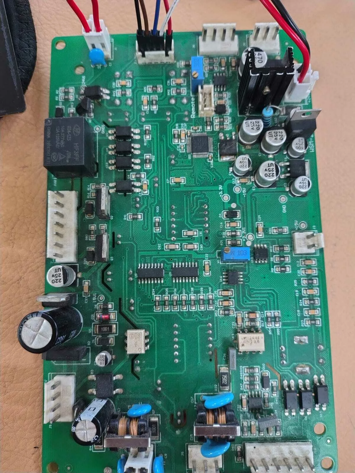
STM32F051C8T6 PWM not generating on custom TIG control board

  • July 29, 2026
  • 19 replies
  • 275 views

I am using the STM32F051C8T6 MCU for TIG welding project, but PWM is not being generated on my custom TIG control board. Can anyone help me so



19 replies

Associate II
July 29, 2026

Are you sure, you call HAL_TIM_Base_Start_IT() for the timer you need?

In your main.c I see only HAL_TIM_Base_Start_IT(&htim3) inside an if()… but HAL_TIM_PWM_Start(&htim14, TIM_CHANNEL_1) for another timer.

Associate II
July 30, 2026

yes i do this thing also but PWM is not working


Andrew Neil
Super User
July 29, 2026

Welcome to the forum

Please see How to write your question to maximize your chances to find a solution for best results.

Please show the schematic of the board.


Before starting on this custom board, have you got the PWM working on an ST board; eg, 

NUCLEO-F031K6

Active

STM32 Nucleo-32 development board with STM32F031K6 MCU, supports Arduino nano connectivity

STM32 Nucleo boards ST

NUCLEO-F042K6

Active

STM32 Nucleo-32 development board with STM32F042K6 MCU, supports Arduino nano connectivity

STM32 Nucleo boards ST

NUCLEO-F072RB

Active

STM32 Nucleo-64 development board with STM32F072RB MCU, supports Arduino and ST morpho connectivity

STM32 Nucleo boards ST


STM32F0DISCOVERY

Active

Discovery kit with STM32F051R8 MCU

STM32 discovery kits ST


via: https://www.st.com/en/microcontrollers-microprocessors/stm32f051c8.html#tools-software


Are you working on the same project as ​@Siddhi here:


A complex system that works is invariably found to have evolved from a simple system that worked.A complex system designed from scratch never works and cannot be patched up to make it work.
Richard Li
Senior
July 29, 2026

I did replay for @Siddni, this code at least with three mistakes,

  • 1. Set TIM3 to PB10 was wrong, PB10 only support TIM2 ch3.​​​​​​​
  • ​​​​​​​2. Didn’t set AFRH moder.
  • 3. TIM3 didn’t set to PWM mode in CCMR1
Associate II
July 30, 2026

but i use a TIM14 for pwm

Richard Li
Senior
July 29, 2026

After read new code, my early comment need update, new code change to TIM14, the CCMR1 setting done. AFRL setting done.

My comment three point fixed.

Associate II
July 30, 2026

please tell me in detail how to set 


Richard Li
Senior
July 30, 2026

In your project, there are two main.c, which one you want use?

This project structure need change, should only one main.c inside.

Richard Li
Senior
July 30, 2026

I did change your project structure, and add code inside TIM14_init, PA5 output come out.

Associate II
July 30, 2026

not working 

Richard Li
Senior
July 30, 2026

Typo, PA4

Richard Li
Senior
July 30, 2026

I didn’t change every code in your project, after TIM14 init, the “__HAL_TIM_SET_COMPARE(&htim14, TIM_CHANNEL_1, 5000);”   the 5000 too big, force TIM14 stop, if you reduce 5000 to 100, it will continual output pulse.

I used debug step by step, before this set 5000, pulse come out.

Please find some one in local help you, your STM32 code knowledge not enough handle this project. 

Andrew Neil
Super User
July 30, 2026

your STM32 code knowledge not enough handle this project. 

+1


@Siddhi  ​@Niva Go back to basics: start with a Nucleo board (or similar); work through basic examples; start simple; add step-by-step

Also:

(those are two different posts in the same thread)

A complex system that works is invariably found to have evolved from a simple system that worked.A complex system designed from scratch never works and cannot be patched up to make it work.
Richard Li
Senior
July 30, 2026

In main.c

I add these code:

Your new project delete these code, of cause it doesn’t work.

If you use Scope measure PA4, you can find pulse come out.

    //RL
    // 1. Enable ARR preload
//    TIM14->CR1 |= TIM_CR1_ARPE;

    // 2. Put channel 1 into output mode
    TIM14->CCMR1 &= ~TIM_CCMR1_CC1S;

    // 3. Enable output compare preload
//    TIM14->CCMR1 |= TIM_CCMR1_OC1PE;

    // 4. Set PWM mode 1 (110b)
    TIM14->CCMR1 &= ~TIM_CCMR1_OC1M;
    TIM14->CCMR1 |= (6 << TIM_CCMR1_OC1M_Pos);

    // 5. Enable channel output
    TIM14->CCER |= TIM_CCER_CC1E;

    // 6. Set ARR and CCR1
    TIM14->ARR = 1000;
    TIM14->CCR1 = 50;

    // 7. Start counter
    TIM14->CR1 |= TIM_CR1_CEN;
//RL

Andrew Neil
Super User
July 30, 2026

@Richard Li Please see:


A complex system that works is invariably found to have evolved from a simple system that worked.A complex system designed from scratch never works and cannot be patched up to make it work.
Richard Li
Senior
July 30, 2026

Attached new code change CCR1 to 5000 fit your original code, it verify by STM32 f0 discovery board , PA4 output pulse frequency 4.8K duty 50%, you can download to F0 discovery test first, maybe your new board with another problem.