How to use STM32 U3 DMA for ADC conversion but using software trigger
Hi All,
I am using STM32U375RETx on in my project on a custom board. I am using 8 channels on ADC1 and 3 on ADC2. I want to scan all the channels using DMA. I have configured the ADCs in scan conversion mode using dma and have also configured the gpdma channels to connect with the ADCs.
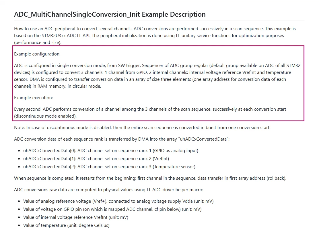
My issue is that I am unable to trigger a scan using software trigger. I am able to trigger a scan only once and then if I scan again, the adc callback is triggered. I verified my adc and gpdma logic by switching from software triggered dma scan to timer event triggered dma scan. This worked and the timer was able to always trigger the adc and update the callback to process the adc data. Could anyone please share what would be an example code for U3 to use software triggered adc dma. The github examples show only for timer trigger and not software trigger[link].
Below is a cleaned up version of my main.c I appreciate any suggestions!
Thanks!
/* USER CODE BEGIN Header */
/**
 ******************************************************************************
 * @file           : main.c
 * @brief          : Main program body
 ******************************************************************************
 * @attention
 *
 * Copyright (c) 2026 STMicroelectronics.
 * All rights reserved.
 *
 * This software is licensed under terms that can be found in the LICENSE file
 * in the root directory of this software component.
 * If no LICENSE file comes with this software, it is provided AS-IS.
 *
 ******************************************************************************
 */
/* USER CODE END Header */
/* Includes ------------------------------------------------------------------*/
#include "main.h"
#include "adc.h"
#include "gpdma.h"
#include "i2c.h"
#include "icache.h"
#include "lptim.h"
#include "tim.h"
#include "usart.h"
#include "gpio.h"

/* Private includes ----------------------------------------------------------*/
/* USER CODE BEGIN Includes */
#include <math.h>
/* USER CODE END Includes */

/* Private typedef -----------------------------------------------------------*/
/* USER CODE BEGIN PTD */

/* USER CODE END PTD */

/* Private define ------------------------------------------------------------*/
/* USER CODE BEGIN PD */
#define VDDA_APPLI (3300UL)

#define ADC_CONVERTED_DATA_BUFFER_SIZE (64UL)

/* Init variable out of expected ADC conversion data range */
#define VAR_CONVERTED_DATA_INIT_VALUE (__LL_ADC_DIGITAL_SCALE(LL_ADC_RESOLUTION_12B) + 1)

/* USER CODE END PD */

/* Private macro -------------------------------------------------------------*/
/* USER CODE BEGIN PM */

/* USER CODE END PM */

/* Private variables ---------------------------------------------------------*/

/* USER CODE BEGIN PV */
extern uint16_t adc1_buf[ADC1_NUM_READINGS];
extern uint16_t adc2_buf[ADC2_NUM_READINGS];
int vref;
__IO uint8_t ubDmaTransferStatus = 2U; /* Variable set into DMA interruption callback */

/* USER CODE END PV */

/* Private function prototypes -----------------------------------------------*/
void SystemClock_Config(void);
/* USER CODE BEGIN PFP */
#if defined(__ICCARM__)
__ATTRIBUTES size_t __write(int, const unsigned char *, size_t);
#endif /* __ICCARM__ */

#if defined(__ICCARM__)
/* New definition from EWARM V9, compatible with EWARM8 */
int iar_fputc(int ch);
#define PUTCHAR_PROTOTYPE int iar_fputc(int ch)
#elif defined(__CC_ARM) || defined(__ARMCC_VERSION)
/* ARM Compiler 5/6*/
#define PUTCHAR_PROTOTYPE int fputc(int ch, FILE *f)
#elif defined(__GNUC__)
#define PUTCHAR_PROTOTYPE int __io_putchar(int ch)
#endif /* __ICCARM__ */

/* USER CODE END PFP */

/* Private user code ---------------------------------------------------------*/
/* USER CODE BEGIN 0 */

/* USER CODE END 0 */

/**
 * @brief  The application entry point.
 * @retval int
 */
int main(void)
{

    /* USER CODE BEGIN 1 */
    uint32_t tmp_index;
    for (tmp_index = 0; tmp_index < ADC1_NUM_READINGS; tmp_index++)
    {
        adc1_buf[tmp_index] = VAR_CONVERTED_DATA_INIT_VALUE;
    }
    for (tmp_index = 0; tmp_index < ADC2_NUM_READINGS; tmp_index++)
    {
        adc2_buf[tmp_index] = VAR_CONVERTED_DATA_INIT_VALUE;
    }

    /* USER CODE END 1 */

    /* MCU Configuration--------------------------------------------------------*/

    /* Reset of all peripherals, Initializes the Flash interface and the Systick. */
    HAL_Init();

    /* USER CODE BEGIN Init */

    /* USER CODE END Init */

    /* Configure the system clock */
    SystemClock_Config();

    /* USER CODE BEGIN SysInit */

    /* USER CODE END SysInit */

    /* Initialize all configured peripherals */
    MX_GPIO_Init();
    MX_GPDMA1_Init();
    MX_ADC1_Init();
    MX_ADC2_Init();
    MX_I2C1_Init();
    MX_USART3_UART_Init();
    MX_USART1_UART_Init();
    MX_ICACHE_Init();
    MX_TIM1_Init();
    MX_LPTIM1_Init();
    MX_TIM6_Init();
    MX_TIM16_Init();
    MX_TIM2_Init();
    MX_LPTIM2_Init();
    /* USER CODE BEGIN 2 */

    /* Perform ADC calibration */
    if (HAL_ADCEx_Calibration_Start(&hadc1, ADC_SINGLE_ENDED) != HAL_OK)
    {
        /* Calibration Error */
        Error_Handler();
    }

    if (HAL_ADCEx_Calibration_Start(&hadc2, ADC_SINGLE_ENDED) != HAL_OK)
    {
        /* Calibration Error */
        Error_Handler();
    }

    if (HAL_ADC_Start_DMA(&hadc1,
                          (uint32_t *)adc1_buf,
                          ADC1_NUM_READINGS) != HAL_OK)
    {
        /* Error: ADC conversion start could not be performed */
        Error_Handler();
    }

    if (HAL_ADC_Start_DMA(&hadc2,
                          (uint32_t *)adc2_buf,
                          ADC2_NUM_READINGS) != HAL_OK)
    {
        /* Error: ADC conversion start could not be performed */
        Error_Handler();
    }

    /* USER CODE END 2 */

    /* Infinite loop */
    /* USER CODE BEGIN WHILE */
    while (1)
    {
        /* If ADC conversions and DMA transfer are completed, then process data */
        if (ubDmaTransferStatus == 1)
        {
            /* Update status variable of DMA transfer */
            ubDmaTransferStatus = 0;

            vref = __HAL_ADC_CALC_VREFANALOG_VOLTAGE(adc1_buf[0], ADC_RESOLUTION_12B);
            int STM_temperature = __HAL_ADC_CALC_TEMPERATURE(VDDA_APPLI, adc2_buf[2], ADC_RESOLUTION_12B);
            printf("STM Temperature(C): %d\r\n", STM_temperature);
        }

        HAL_Delay(500);

        /* USER CODE END WHILE */

        /* USER CODE BEGIN 3 */
    }
    /* USER CODE END 3 */
}

/**
 * @brief System Clock Configuration
 * @retval None
 */
void SystemClock_Config(void)
{
    RCC_OscInitTypeDef RCC_OscInitStruct = {0};
    RCC_ClkInitTypeDef RCC_ClkInitStruct = {0};

    /** Enable Epod Booster
     */
    if (HAL_RCCEx_EpodBoosterClkConfig(RCC_EPODBOOSTER_SOURCE_MSIS, RCC_EPODBOOSTER_DIV1) != HAL_OK)
    {
        Error_Handler();
    }
    if (HAL_PWREx_EnableEpodBooster() != HAL_OK)
    {
        Error_Handler();
    }

    /** Configure the main internal regulator output voltage
     */
    if (HAL_PWREx_ControlVoltageScaling(PWR_REGULATOR_VOLTAGE_SCALE1) != HAL_OK)
    {
        Error_Handler();
    }

    /** Set Flash latency before increasing MSIS
     */
    __HAL_FLASH_SET_LATENCY(FLASH_LATENCY_2);

    /** Initializes the CPU, AHB and APB buses clocks
     */
    RCC_OscInitStruct.OscillatorType = RCC_OSCILLATORTYPE_LSI | RCC_OSCILLATORTYPE_MSIS;
    RCC_OscInitStruct.LSIState = RCC_LSI_ON;
    RCC_OscInitStruct.LSIDiv = RCC_LSI_DIV1;
    RCC_OscInitStruct.MSISState = RCC_MSI_ON;
    RCC_OscInitStruct.MSISSource = RCC_MSI_RC0;
    RCC_OscInitStruct.MSISDiv = RCC_MSI_DIV1;
    if (HAL_RCC_OscConfig(&RCC_OscInitStruct) != HAL_OK)
    {
        Error_Handler();
    }

    /** Initializes the CPU, AHB and APB buses clocks
     */
    RCC_ClkInitStruct.ClockType = RCC_CLOCKTYPE_HCLK | RCC_CLOCKTYPE_SYSCLK | RCC_CLOCKTYPE_PCLK1 | RCC_CLOCKTYPE_PCLK2 | RCC_CLOCKTYPE_PCLK3;
    RCC_ClkInitStruct.SYSCLKSource = RCC_SYSCLKSOURCE_MSIS;
    RCC_ClkInitStruct.AHBCLKDivider = RCC_SYSCLK_DIV1;
    RCC_ClkInitStruct.APB1CLKDivider = RCC_HCLK_DIV1;
    RCC_ClkInitStruct.APB2CLKDivider = RCC_HCLK_DIV1;
    RCC_ClkInitStruct.APB3CLKDivider = RCC_HCLK_DIV1;

    if (HAL_RCC_ClockConfig(&RCC_ClkInitStruct, FLASH_LATENCY_2) != HAL_OK)
    {
        Error_Handler();
    }
}

/* USER CODE BEGIN 4 */
/**
 * @brief  Retargets the C library printf function to the USART.
 * @param  None
 * @retval None
 */
PUTCHAR_PROTOTYPE
{
    /* Place your implementation of fputc here */
    /* e.g. write a character to the USART1 and Loop until the end of transmission */
    HAL_UART_Transmit(&huart3, (uint8_t *)&ch, 1, 0xFFFF);

    return ch;
}

#if defined(__ICCARM__)
size_t __write(int file, unsigned char const *ptr, size_t len)
{
    size_t idx;
    unsigned char const *pdata = ptr;

    for (idx = 0; idx < len; idx++)
    {
        iar_fputc((int)*pdata);
        pdata++;
    }
    return len;
}
#endif /* __ICCARM__ */

/**
 * @brief  DMA transfer complete callback
 * @note   This function is executed when the transfer complete interrupt
 *         is generated
 * @retval None
 */
void HAL_ADC_ConvCpltCallback(ADC_HandleTypeDef *hadc)
{
    /* Update status variable of DMA transfer */
    ubDmaTransferStatus = 1;
}

/**
 * @brief  ADC error interruption callback
 * @retval None
 */
void HAL_ADC_ErrorCallback(ADC_HandleTypeDef *hadc)
{
    /* Note: Disable ADC interruption that caused this error before entering in
             infinite loop below. */

    /* In case of error due to overrun: Disable ADC group regular overrun interruption */
    LL_ADC_DisableIT_OVR(ADC1);
    LL_ADC_DisableIT_OVR(ADC2);

    /* Error reporting */
    Error_Handler();
}

/* USER CODE END 4 */

/**
 * @brief  This function is executed in case of error occurrence.
 * @retval None
 */
void Error_Handler(void)
{
    /* USER CODE BEGIN Error_Handler_Debug */
    /* User can add his own implementation to report the HAL error return state */
    __disable_irq();
    while (1)
    {
    }
    /* USER CODE END Error_Handler_Debug */
}
#ifdef USE_FULL_ASSERT
/**
 * @brief  Reports the name of the source file and the source line number
 *         where the assert_param error has occurred.
 * @param  file: pointer to the source file name
 * @param  line: assert_param error line source number
 * @retval None
 */
void assert_failed(uint8_t *file, uint32_t line)
{
    /* USER CODE BEGIN 6 */
    /* User can add his own implementation to report the file name and line number,
       ex: printf("Wrong parameters value: file %s on line %d\r\n", file, line) */
    /* USER CODE END 6 */
}
#endif /* USE_FULL_ASSERT */