Associate II
June 14, 2026
Solved

How should the FMAC of STM32G474 be configured to obtain correct calculation data?

  • June 14, 2026
  • 4 replies
  • 177 views

Hi,

I encountered problems during the development process of using FMAC. To illustrate the problem simply, I used FMAC to implement an RC filter, by which I mean to illustrate the calculation problems of FMAC.

RC filter:10K+10nF
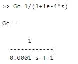
Its discrete z-domain expression:(Ts=1e-6,Tustin)
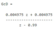
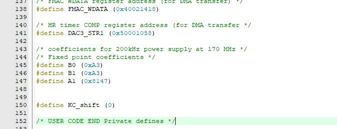
so I get fixed-point parameters :
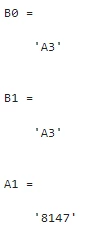
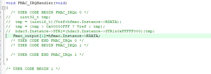
I referred to the example program of AN5305 and used a 1-us timer to trigger ADC sampling. After the ADC sampling is completed, DMA writes to the WriteData of FMAC, and then the ReadData is processed in the interrupt as follows:
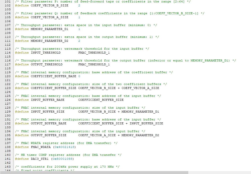
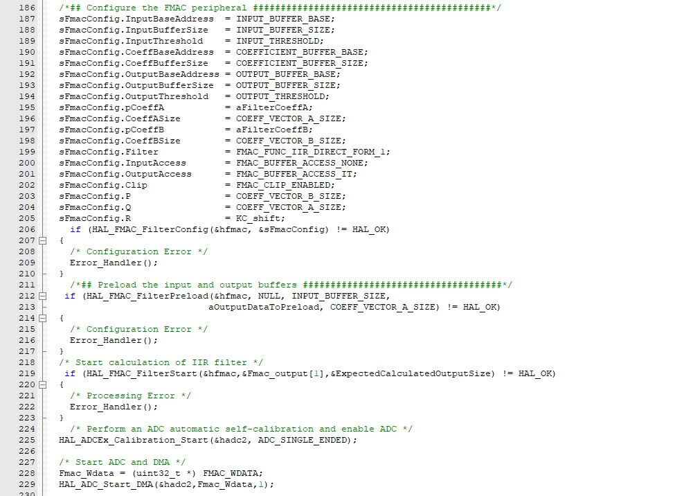
As shown above, my current ADC sample is 0, and my Vref is set to 800. I think the output of FMAC as an RC filter should be around 800 in the DC case, but actually it is not. It is a relatively small value. Why is that?
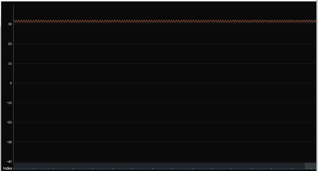
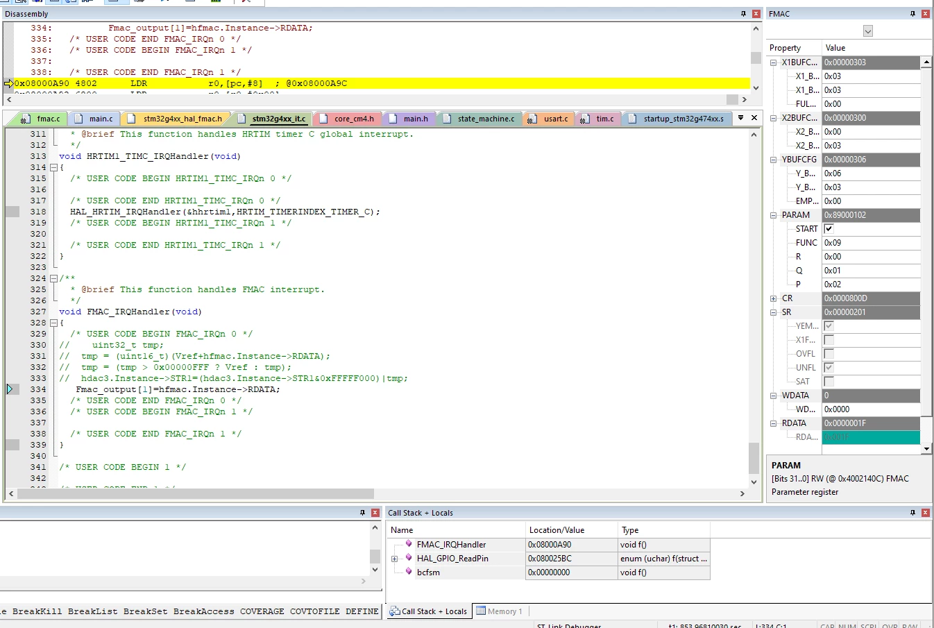
May I ask if there is a problem with my configuration of FMAC?


Best answer by Saket_Om

Hello ​@TakingLee 

Please found some issues or incoherence in your code that could be the cause of your dysfonctionnement:
    1- HAL_FMAC_FilterPreload is called with the wrong parameters.
        aInputValues is sized with ARRAY_SIZE (1) but INPUT_BUFFER_SIZE is 3.
        This may cause the function to read two values beyond the array.
    2- HAL_FMAC_FilterStart is called with the wrong parameters
        With your FMAC configuration, the expected output size should configure the number of data for DMA transfer.
        If you want a one-shot operation, use 1U.
    3- error in CNTRL_1p1zFloat:
        The local variable "acc" is not initialized and you did a first "+=" operation. The result could be unpredictable.
        I recommend making an initial assignment instead of a compoud assignment.
    4- FMAC works with Q1.15 format data, while your "CNTRL_1p1zFloat" function works in float data. 
        This may naturally create small differences in results.
    5- The A1 coefficient is inconsistent:
         - For FMAC, the coefficient A1 is set to 0x8147 (Q1.15 format) which is the approxmatively the float value -0.989.
         - For CNTRL_1p1zFloat, the coefficient A1 is set to the float value +0.99 which is the 0x7EB8 in Q1.15 format.
         
        The FMAC implements the IIR formula: IIR filter Y = B*X + A*Y’. By using a negative A coefficient the formula is resume to Y = B*X - A*Y’
        Then if this equation is fine for you, then CNTRL_1p1zFloat should used the same negative value.
        Otherwise, if you want the initial IIR filter formula Y = B*X + A*Y’, then you must use a positive coefficient
        
        Which coefficicent do you want to keep?


Best regards

Omar

4 replies

ST Technical Moderator
June 18, 2026

Hello ​@TakingLee 

About your question "May I ask if there is a problem with my configuration of FMAC?" and based on the information provided, the FMAC configuration seems to be correct.
 
A quick reminder regarding the use of variables in callbacks: they must be declared as "volatile".
Then we invite you to verify that the "Fmac_output" array is correctly declared as volatile in your application.
 
Otherwise, about your problem, we have no enough data to make a correct analysis.
Then could you give us more details about your ADC configuration ?
What sampling time is it using ?
Is the raw ADC measurement correct relative to your input signal ?
 

In order to give better visibility on the answered topics, please click on 'Best answer' on the reply which solved your issue or answered your question. Saket_Om
TakingLeeAuthor
Associate II
June 21, 2026

Hello,

Thanks for your answers.

Please refer to the attachment for relevant project codes. As shown in the figure above, the calculation result of FMAC is different from that calculated by the software. In this project, the period time of Timer6 is set to 10 μs. FMAC is calculated once and calculated by the software method once every 10 μs. This project is modified from the official ST example program.

Why are the calculation results of the FMAC module different from those of the software mode?

Saket_OmBest answer
ST Technical Moderator
June 24, 2026

Hello ​@TakingLee 

Please found some issues or incoherence in your code that could be the cause of your dysfonctionnement:
    1- HAL_FMAC_FilterPreload is called with the wrong parameters.
        aInputValues is sized with ARRAY_SIZE (1) but INPUT_BUFFER_SIZE is 3.
        This may cause the function to read two values beyond the array.
    2- HAL_FMAC_FilterStart is called with the wrong parameters
        With your FMAC configuration, the expected output size should configure the number of data for DMA transfer.
        If you want a one-shot operation, use 1U.
    3- error in CNTRL_1p1zFloat:
        The local variable "acc" is not initialized and you did a first "+=" operation. The result could be unpredictable.
        I recommend making an initial assignment instead of a compoud assignment.
    4- FMAC works with Q1.15 format data, while your "CNTRL_1p1zFloat" function works in float data. 
        This may naturally create small differences in results.
    5- The A1 coefficient is inconsistent:
         - For FMAC, the coefficient A1 is set to 0x8147 (Q1.15 format) which is the approxmatively the float value -0.989.
         - For CNTRL_1p1zFloat, the coefficient A1 is set to the float value +0.99 which is the 0x7EB8 in Q1.15 format.
         
        The FMAC implements the IIR formula: IIR filter Y = B*X + A*Y’. By using a negative A coefficient the formula is resume to Y = B*X - A*Y’
        Then if this equation is fine for you, then CNTRL_1p1zFloat should used the same negative value.
        Otherwise, if you want the initial IIR filter formula Y = B*X + A*Y’, then you must use a positive coefficient
        
        Which coefficicent do you want to keep?


Best regards

Omar

In order to give better visibility on the answered topics, please click on 'Best answer' on the reply which solved your issue or answered your question. Saket_Om
TakingLeeAuthor
Associate II
June 24, 2026

Hello,@Saket_Om

Thank you for your answer. My problem has been solved. 

INPUT_BUFFER_SIZE shall be 2, and A1 shall be negative; that is, as you said, A1 shall be +0.99 (0x7EB8).

Thank you very much.