


Hi, I'm working on ST-NUCLEO G071RB with DRP1M1 board. The USB-PD negotiation is successful as attached image shown but no current is being drawn from the external PSU to the sink device (which is a power bank). Please provide solution/support, thank
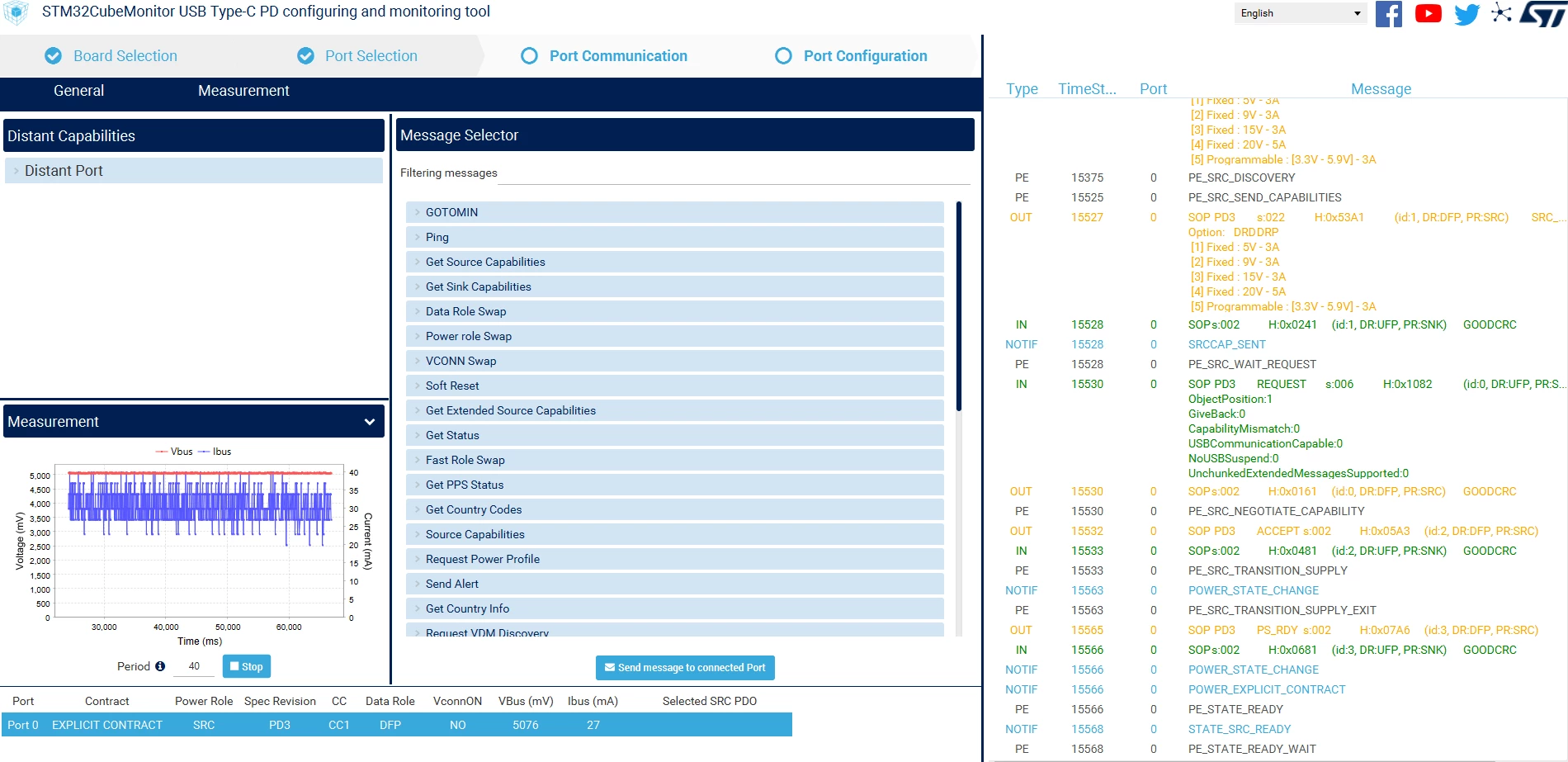
Thank you for your support but still I couldn't charge the power bank with the quick fix given. I'll show you my setup, I'm not sure what else is missing out for the external PSU to supply the current. Please advise, thank you very much.
I tried to reproduce your case connecting an SNK1M1 to the DRP1M1. The sink device is loaded by a variable resistor.
The contract is in 5V and we can observe the current is rising as I increase the load.
But, I can observe on your power supply and on the measurement that you are started negotiation under 15V.
The negotiation should occur under default 5V as in the example below where you can observe 4 phases,
- before connection
- The negotiation
- The power supply ramp up
- The steady state at 20V
This can explain why the power bank does not charge.
Please can you try supplying your DRP under 5V, and perhaps increase the SINK load with an external resistor ?
The STEVAL-2STPD01 is a USB Type-C Power delivery dual port adapter. This can be an example for the Provider side of your dual role Power delivery device.
Thank you for your support, I can now get the external PSU to supply current. However, I can charge type A pd power bank but not type B pd power bank. Type A power bank is a commercial power bank as you can see in the figure below, I swap the power role to SNK role after connected and hard reset it afterwards while type B power bank's USB C port is only designed to be charged, so no power role swap is performed. Do you have any ideas/thoughts on this? Thank you.
Reading your traces, I can see that both power banks communicates in USBPD. They are both well connected as SINK.
Type A power bank selected PDO Number 2 (TimeStamp 38100 - objectPosition 2): so 9V - But due to the DRP1M1 board supply, the measurement is 5V, and up to 1.5 or 1.6A.
Reading the measurement graph, It seems you manually change the DRP1M1 supply voltage to 9V and back to 5V during the test ?
Type B power bank selected PDO Number 1 (TimeStamp 21753 - ObjectPosition 1): so 5V - And it current measurement is 30mA - The DRP1M1 does not limit the current under 3A in this case: it means that the battery does not request more current. It looks like an already charged battery.
I understand this is not the behavior you expected please can you explain. Also what Type A or type B power bank stand for ? What is their difference ? construction / interface ?
Thank you for your support. Let's forget about the Type A power bank above, it's basically a random brand power bank in the market while Type B power bank is company's product. In short, my goal is to charge the company's power bank with different voltages such as 5V/9V/15V/20V. However, the external power supply is not supplying current to the power bank even though the pd communication is completed. In addition, with the exact same setup, the external power supply would supply current if I connected it to random brand power bank in the market or my phone. It would be great if you could find any clues from the traces that could explain the behaviors. I'll share you the traces for different cases at below. Hope it clears the picture and please request for more info if needed, thank you.
Figure1: Company's power bank UCPD trace
Remark:
1) The company's power bank is not fully charged. If I use a 100W USB pd charger to charge it, it could receive 20V with 5A current.