Solved
Half Word Transfer (DMA) not working on STM32G431KBT6
Hi everyone,
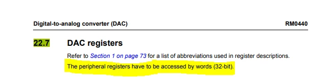
I'm using an STM32G431KBT6 MCU (STM32G4 Series) and I'm trying to generate a sine wave of 1 kHz using DAC and DMA . I've initialized the DMA as a half word, but it's not creating a sine wave. When I switch to word, it works perfectly. Can anyone help me figure out what's going on?
My SYSCLK is at 16MHz. I have put Prescalar as 0 and ARR to 124 for generation of 1 KHz sine wave.
I've attached my code snippet below for reference.
#include "main.h"

#define SINE_TABLE_SIZE 128

DAC_HandleTypeDef hdac1;
DMA_HandleTypeDef hdma_dac1_ch1;

TIM_HandleTypeDef htim2;

const uint16_t sineLookupTable[SINE_TABLE_SIZE] = {
2048, 2148, 2248, 2348, 2447, 2545, 2642, 2737, 2831, 2923, 3013, 3100, 3185, 3267, 3346, 3423,
3495, 3565, 3630, 3692, 3750, 3804, 3853, 3898, 3939, 3975, 4007, 4034, 4056, 4073, 4085, 4093,
4095, 4093, 4085, 4073, 4056, 4034, 4007, 3975, 3939, 3898, 3853, 3804, 3750, 3692, 3630, 3565,
3495, 3423, 3346, 3267, 3185, 3100, 3013, 2923, 2831, 2737, 2642, 2545, 2447, 2348, 2248, 2148,
2048, 1947, 1847, 1747, 1648, 1550, 1453, 1358, 1264, 1172, 1082, 995, 910, 828, 749, 672,
600, 530, 465, 403, 345, 291, 242, 197, 156, 120, 88, 61, 39, 22, 10, 2,
0, 2, 10, 22, 39, 61, 88, 120, 156, 197, 242, 291, 345, 403, 465, 530,
600, 672, 749, 828, 910, 995, 1082, 1172, 1264, 1358, 1453, 1550, 1648, 1747, 1847, 1947};


void SystemClock_Config(void);
static void MX_GPIO_Init(void);
static void MX_DMA_Init(void);
static void MX_DAC1_Init(void);
static void MX_TIM2_Init(void);

int main(void)
{

HAL_Init();

SystemClock_Config();

MX_GPIO_Init();
MX_DMA_Init();
MX_DAC1_Init();
MX_TIM2_Init();

HAL_DAC_Start_DMA(&hdac1,DAC_CHANNEL_1,(uint32_t*)sineLookupTable,SINE_TABLE_SIZE,DAC_ALIGN_12B_R);
HAL_TIM_Base_Start(&htim2);

while (1);
}

void HAL_DAC_MspInit(DAC_HandleTypeDef* hdac)
{
GPIO_InitTypeDef GPIO_InitStruct = {0};
if(hdac->Instance==DAC1)
{
__HAL_RCC_DAC1_CLK_ENABLE();
__HAL_RCC_GPIOA_CLK_ENABLE();
GPIO_InitStruct.Pin = GPIO_PIN_4;
GPIO_InitStruct.Mode = GPIO_MODE_ANALOG;
GPIO_InitStruct.Pull = GPIO_NOPULL;
HAL_GPIO_Init(GPIOA, &GPIO_InitStruct);
hdma_dac1_ch1.Instance = DMA1_Channel1;
hdma_dac1_ch1.Init.Request = DMA_REQUEST_DAC1_CHANNEL1;
hdma_dac1_ch1.Init.Direction = DMA_MEMORY_TO_PERIPH;
hdma_dac1_ch1.Init.PeriphInc = DMA_PINC_DISABLE;
hdma_dac1_ch1.Init.MemInc = DMA_MINC_ENABLE;
hdma_dac1_ch1.Init.PeriphDataAlignment = DMA_PDATAALIGN_HALFWORD;
hdma_dac1_ch1.Init.MemDataAlignment = DMA_MDATAALIGN_HALFWORD;
hdma_dac1_ch1.Init.Mode = DMA_CIRCULAR;
hdma_dac1_ch1.Init.Priority = DMA_PRIORITY_HIGH;
if (HAL_DMA_Init(&hdma_dac1_ch1) != HAL_OK)
{
Error_Handler();
}
__HAL_LINKDMA(hdac,DMA_Handle1,hdma_dac1_ch1);
}
}

static void MX_TIM2_Init(void)
{
 TIM_ClockConfigTypeDef sClockSourceConfig = {0};
 TIM_MasterConfigTypeDef sMasterConfig = {0};

 htim2.Instance = TIM2;
 htim2.Init.Prescaler = 0;
 htim2.Init.CounterMode = TIM_COUNTERMODE_UP;
 htim2.Init.Period = 124;
 htim2.Init.ClockDivision = TIM_CLOCKDIVISION_DIV1;
 htim2.Init.AutoReloadPreload = TIM_AUTORELOAD_PRELOAD_DISABLE;
 if (HAL_TIM_Base_Init(&htim2) != HAL_OK)
 {
 Error_Handler();
 }
 sClockSourceConfig.ClockSource = TIM_CLOCKSOURCE_INTERNAL;
 if (HAL_TIM_ConfigClockSource(&htim2, &sClockSourceConfig) != HAL_OK)
 {
 Error_Handler();
 }
 sMasterConfig.MasterOutputTrigger = TIM_TRGO_UPDATE;
 sMasterConfig.MasterSlaveMode = TIM_MASTERSLAVEMODE_DISABLE;
 if (HAL_TIMEx_MasterConfigSynchronization(&htim2, &sMasterConfig) != HAL_OK)
 {
 Error_Handler();
 }
}