

Lars Beiderbecke
Senior III
January 10, 2019
Question

FatFs/SDMMC with 4 wires times out, 1 wire works

  • January 10, 2019
  • 11 replies
  • 5200 views

I'm still trying to get FatFs to work with 4 wires. My PCB has been properly traced, each line is within a few mm of all others, and has a 33K pull-up. Internal pull-ups are off.

This setup works fine at full-speed (45 MHz) when using only 1 wire, but when I select all 4 wires in CubeMX, the code hangs in stm32f7xx_hal_sd.c, in the /* Poll on SDMMC flags */ loop. It probably should time out, but doesn't. This doesn't change if I lower the speed to 3 MHz.

My concern is not the timeout, though, but why 4 wires are still not working. Could someone advise on my PCB if everything is alright there? Are the pull-ups placed OK? The SD1 trace accidentally hit the resistor pad, but is this already enough to mess everything up?
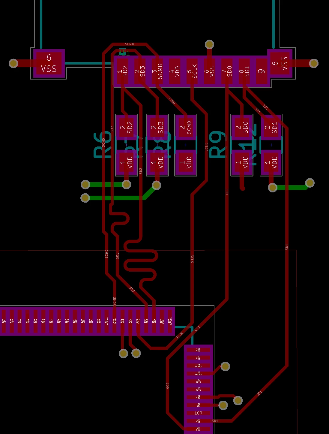
0690X000006D1yYQAS.png(Note that seemingly unconnected resistors are connected by copper pours.)

This topic has been closed for replies.

11 replies

Tesla DeLorean
Guru
January 10, 2019

With better routing you could have entirely lost those stub traces to the resistors.

On the settings you can try turn off the pull-up at the STM32 pin, and also reduce the slew-rate (speed) that you're driving into relatively short traces. The GPIO_SPEED_FREQ_VERY_HIGH setting is likely to cause ringing/overshoot.

Tips, Buy me a coffee, or three.. PayPal Venmo (See Profile) Up vote any posts that you find helpful, it shows what's working..
Lars Beiderbecke
Senior III
January 10, 2019

Thanks, I've decreased the speed to "high" now. Alas, this didn't solve the problem.

What kind of routing would you recommend? Like the one I used for SD3? Since the upper half is blocked by the uSD connector, I placed the pull-ups below. I realized later that these are no caps, and can be placed further away, up to the side of the uSD connector.

Tesla DeLorean
Guru
January 10, 2019

>>What kind of routing would you recommend?

Feed thru on the the pad, ie in one side, out the other, rather the out and back excursion.

Not entirely sure this is a routing issue, I can push much higher frequencies down 3" leads.

Clocking the SDMMC peripheral at 45 MHz, or SCLK at 45 MHz via ClockDiv?

Presuming PC8..12 for D0..D3,CLK and PD2 CMD

What is your HSE source? What USART pins for debugging?

Tips, Buy me a coffee, or three.. PayPal Venmo (See Profile) Up vote any posts that you find helpful, it shows what's working..
Lars Beiderbecke
Senior III
January 10, 2019

Got it, thanks!

I'm using HSI, HCLK is 190 MHz, and SDMMC1 is 47.5 MHz. I currently bypass the extra SDMMCCLK divider, but tested down to /32.

Pins are correct, logging is UART6, only RX/TX. Thanks!

Steve Melnikoff
Senior
April 5, 2019