

Associate II
January 30, 2024
Question

Communication between two stm32 boards

  • January 30, 2024
  • 19 replies
  • 14553 views


Hello Everyone,

I'm reaching out for some guidance on a project that I've been working on. Despite considerable effort, I'm still struggling to find an effective solution.

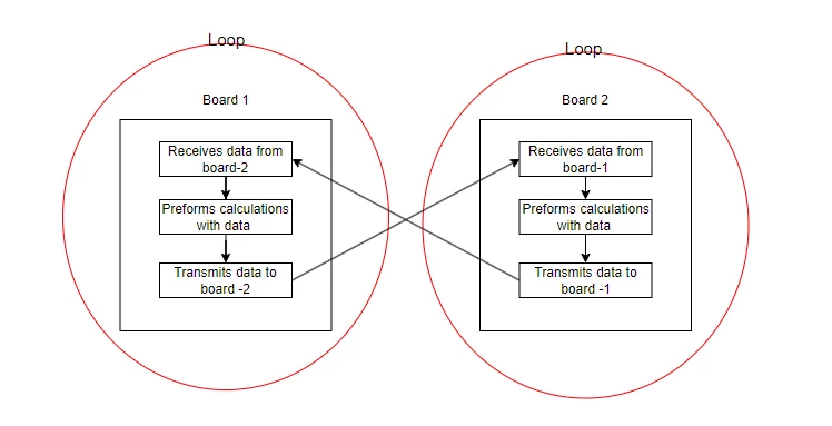
My project involves developing a controller design to manage different models on each STM32 microcontroller. The goal is to synchronize these controllers. I have successfully built the models, and they are functioning well. The key task is for each board to transmit data to another board. This data is crucial for calculations, leading to the generation of new data. This process of data exchange needs to be continuous. The image below shows how the each stm32 work. 
CircuitFreak_1-1706636236779.png

Here's the challenge: I'm having difficulties with the data transmission and reception between the boards. The data, which is in double format.

I would greatly appreciate any advice or suggestions on this matter, as I'm starting to run low on ideas.

Thank you in advance!


P.S. This is the code i am using for both boards. Just to check if i can transmit and receive at the same time. 

CircuitFreak_0-1706646591206.png


This topic has been closed for replies.

19 replies

TDK
January 30, 2024

Where is the entry point for the loop?

"If you feel a post has answered your question, please click ""Accept as Solution""."
Associate II
January 30, 2024

Each board has it own initial conditions. The it goes into he while(1) loop. Does this answer your question? 

Andrew Neil
Super User
January 30, 2024

So how are you connecting the 2 boards - UART? Other?

They key to this kind of thing is to not try to do both ends at once!

Start by getting one end working & fully tested against, say, a terminal in a PC.

Then get the other  end working & fully tested against, say, a terminal in a PC.

Then - and only then - bring the two together.

A complex system that works is invariably found to have evolved from a simple system that worked.A complex system designed from scratch never works and cannot be patched up to make it work.
Associate II
January 30, 2024

I have tired both SPI & and UART. When I loop the connection onto itself. It works fine. I checked this by sending the data the serial comms thru UART. The trouble happens when I make the connect from board 1 to board 2. 

Karl Yamashita
Principal
January 30, 2024

Sounds like a hardware issue possibly. Show us a diagram on how you're connecting the boards together with PS.

If a reply has proven helpful, click on Accept as Solution so that it'll show at top of the post.CAN Jammer an open source CAN bus hacking toolCANableV3 Open Source
Bob S
Super User
January 30, 2024

What trouble?  You haven't given us any info on what is or is not happening.  Nor have you shown any code (hint: use the code format button, click on "..." then "</>").

What do you see that you don't expect?  What don't you see that you do expect?

Associate II
January 30, 2024

i not sure where "..." is. The trouble is that i can figure out how to send and receive. The figure above shows that.  

Andrew Neil
Super User
January 31, 2024

@CircuitFreak wrote:

i not sure where "..." is. .  


It's here:

AndrewNeil_2-1706693574443.png

After you press it, you get an extra set of icons - including the one for posting source code:

AndrewNeil_3-1706693621074.png


A complex system that works is invariably found to have evolved from a simple system that worked.A complex system designed from scratch never works and cannot be patched up to make it work.
Pavel A.
January 30, 2024

Here you can find help with your project, both in hardware and software.

Tesla DeLorean
Guru
January 30, 2024

Use circular buffers to transmit pending data, and receive it.

Use a protocol like SLIP, which is self synchronizing, so that you can send packets back and forth. Feed whole packets to your processing loop.

Have some method to track if you've lost packets, and either request new copies, or have some recovery scheme to rebroadcast or heart-beat, should the link go down or lose bytes/synchronization.

Tips, Buy me a coffee, or three.. PayPal Venmo (See Profile) Up vote any posts that you find helpful, it shows what's working..
Andrew Neil
Super User
January 31, 2024

@CircuitFreak wrote:

P.S. This is the code i am using for both boards. Just to check if i can transmit and receive at the same time. 

CircuitFreak_0-1706646591206.png


The fundamental problem there is that you have no synchronisation between your sender & receiver.

You just arbitrarily send - without knowing that the other end is ready to receive!

As @Tesla DeLorean said, you need some sort of protocol to ensure that the receiver has received all that the sender sent - nothing more, and nothing less, and without errors.

A complex system that works is invariably found to have evolved from a simple system that worked.A complex system designed from scratch never works and cannot be patched up to make it work.
Associate II
January 31, 2024

Thanks, Yes i am quite certain that is the issue. I dont know how to overcome this? Is there any techniques i could used? 

Karl Yamashita
Principal
January 31, 2024

You still haven't shown any diagram. With the two SPI devices, you need to have a ground reference, again without a diagram, we don't know if you wired it correctly.


With SPI bus, technically one of your boards needs to be configured as the Master and the other needs to be the Slave. The slave needs to be able to signal the Master there is data available to be sent to it. When the Master gets a signal (GPIO interrupt), the Master can clock the data from the slave to the master. 


Without this signal, you can have the Master still clock data from the slave, but the slave may not have any valid data at that time. You could essentially get away without a signal from the slave but then you're now getting into writing a protocol, usually with a size/checksum to know you have valid packet. 

If a reply has proven helpful, click on Accept as Solution so that it'll show at top of the post.CAN Jammer an open source CAN bus hacking toolCANableV3 Open Source