SUrte.1
Associate II
Aug 25, 2022 7:42 AM UTC
Question

Acknowledgement Error in CAN Communication

Hello there,

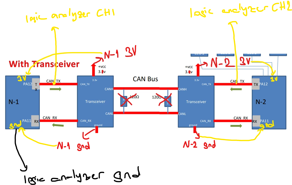
I am newbie in CAN communication. Although there is no problem in loopback mode, I get acknowledgment error in normal mode. For this reason, the tx message I sent continues to be sent because it was not ACKed, and after a while, all mailboxes fill up and the HAL_ADDTX function returns HAL_CAN_ERROR_PARAM. When I check the LEC register, I get Acknowledgment Error. I shared the diagram I used and my codes. You can review the main.c msp.c and it.c files on the Github link. The reason I don't use 120 ohms between CANH and CANL is because it's in my cjmcu230(with SN65HVD230) transciever module. I am using the same code on two STM32F429 boards. Thank you in advance for your help.

Github Link:

https://github.com/niekiran/MasteringMCU2/tree/master/Source_codes/OpenStm32SWB/MasteringMCU2/CAN_Normal_Mode_2Nodes

My Diagram:

0693W00000QOORrQAP.png 

CANTx logic signals in my logic analyzer(you can see it keep repeats the same msg):

0693W00000QOOU2QAP.png 

This topic has been closed for replies.

12 replies

TThan
Associate III
Aug 25, 2022 10:29 AM UTC

Hi SUrte.1

at first glance it looks like a hardware I assume with CAN:RX you mean the R output of the CAN Transceiver chips. Did you measure the RX-line coming from the N2 reveiver chip? It should be the same signal as the one you are sending out and viewing at CH1.

I assume there might be a disturbed outpu, Since you are operating the CAN trnasceivers at the very lower end of the allowed power supply.

Best regards

Thomas

SUrte.1
SUrte.1Author
Associate II
Aug 25, 2022 11:07 AM UTC

First of all, thank you very much for your answer.

The CH-1 signal is the CANTx signal found in N-1. The CH-2 signal is the CANTx signal in N-2. My purpose in these connections was to see that after the Tx signal I sent from N-1, the necessary ack signal came from the Tx signal in N-2. However, as you can see that the tx message is constantly repeated because the necessary ack signal does not come from N-2. And I also thought about the problem that might be caused by using 3V, but this is the maximum voltage I can get from the stm32f429 pins and I am afraid of that how can I increase it or if I increase it, I can disrupt the Rx Tx signals from PA11 and PA12. But right now I suspect most of my transcievers are corrupt.

mƎALLEm
ST Technical Moderator
Aug 25, 2022 10:32 AM UTC

Hello,

Check all your wiring continuity .. If it's ok, I doubt there is an issue with the module. Someone has raised an issue with CJMCU230 module with a counterfeit SN65HVD230 part. So check this video out:

https://www.youtube.com/watch?v=PR9pgjWre-Q

To give better visibility on the answered topics, please click "Best answer" on the reply which solved your issue or answered your question.
SUrte.1
SUrte.1Author
Associate II
Aug 25, 2022 11:11 AM UTC

Hello,

Thank you very much for your reply. I was also suspecting the transceiver. Do you have a suggestion for a transceiver module that can work using the same method?