
Associate II
September 1, 2026
Solved

Supply STM32L053R8 on NUCLE-L053R8 at 1.8V

  • September 1, 2026
  • 4 replies
  • 49 views

Hello,


As indicate in the title I am trying to supply the MCU STM32L053R8 at 1.8V on the devkit NUCLEO-L053R8.

To do it I opened Jumper JP6, which purposes is to monitor current, and I deliver 1.8V on the VDD signal.

But the MCU is not working when I do that, my power supply is able to show me consumption and it stays to 0. 
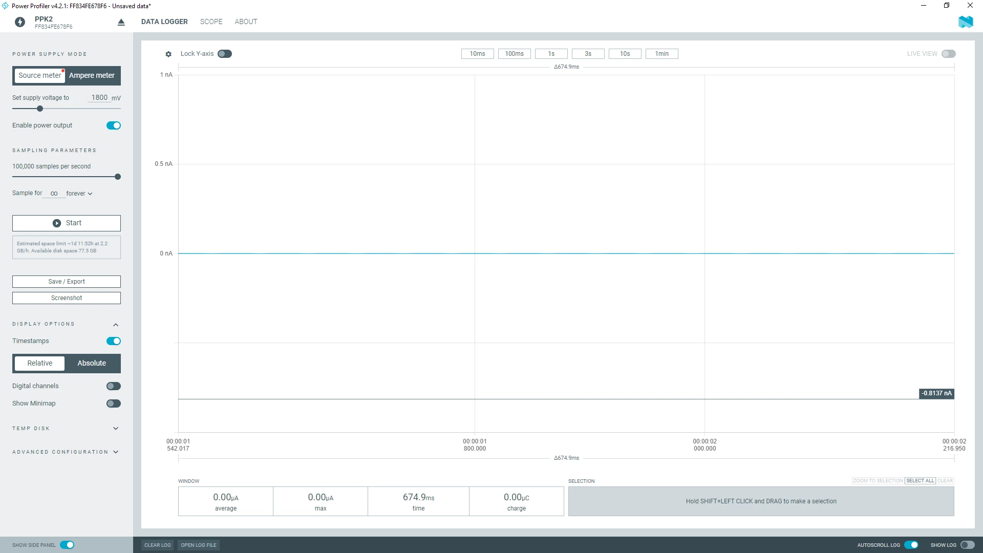
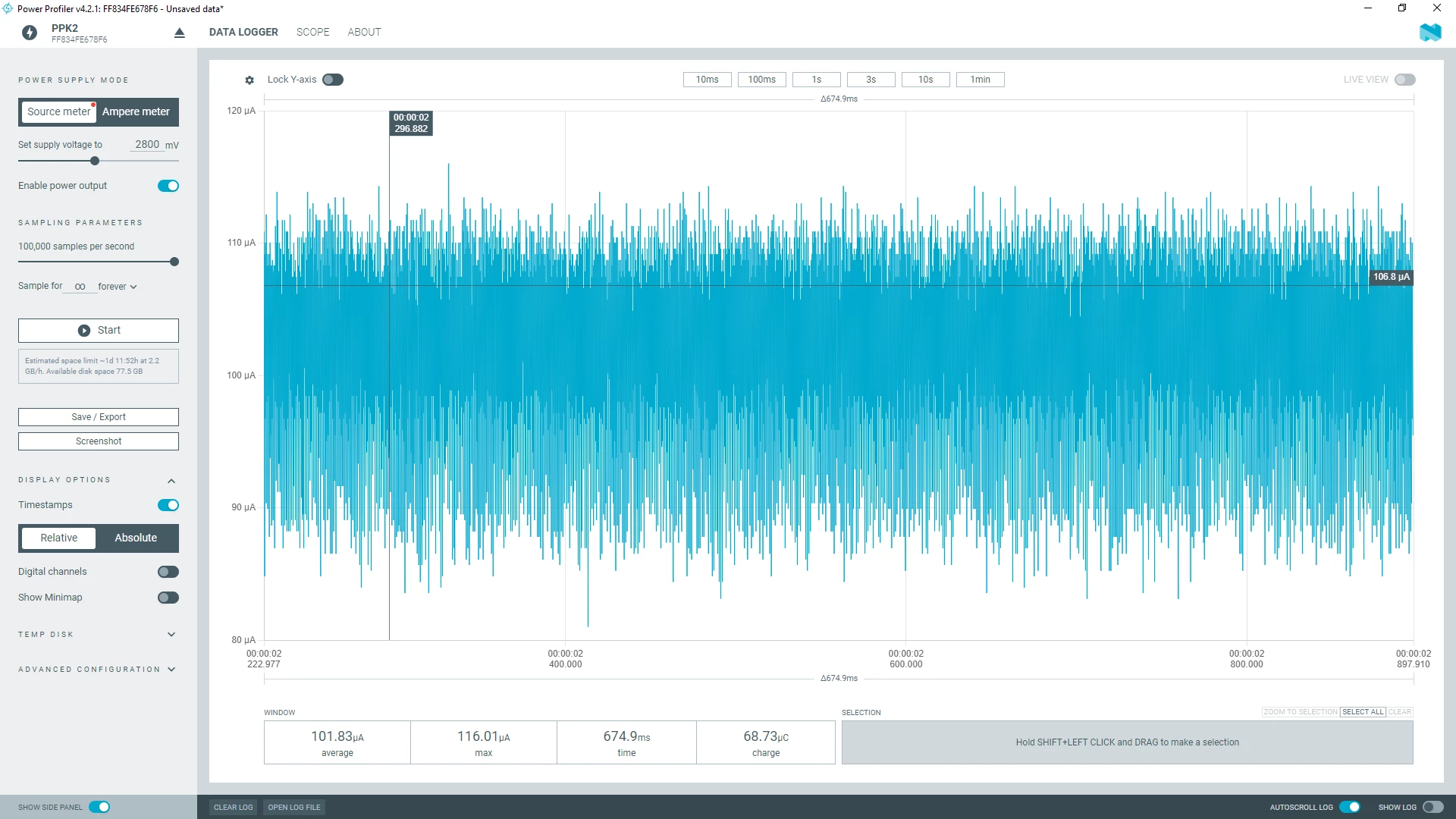
I need to level up at minimum 2.8V to see some current consumption.
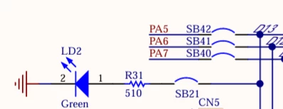
Is there anything in particular  I need to disconnect to be able to power it at 1.8V ? I’ve tried to open SB21 to disconnect the Green Led connected to the MCU but it did not change anything.
 

Also, I’ve try every power range and using MSI RC as SYSCLK.

Please found attached my firmware which is, basicaly, only a while(1).


Best Regards

Thibaud

Best answer by Tiboww

Thank you for your help,


I needed to unplug the USB_PWR connector so ST_Link does not turn on and open SB31 so current does not go to STLink through NRST signal.


Best Regards

Thibaud

4 replies

Andrew Neil
Super User
September 1, 2026

You need to study the schematics carefully.

I think the ST-Link works only at 3V, so you will probably need to disconnect it - in particular, the nRST signal from ST-Link to target.

It might be best to break-off the ST-Link section … ?


my power supply is able to show me consumption and it stays to 0

What’s the resolution on that ?

Edit: Never mind - I see it’s a Nordic PPK2.


PS:

May also need to remove SB2:

https://www.st.com/resource/en/user_manual/um1724-stm32-nucleo64-boards-mb1136-stmicroelectronics.pdf#page=23

via: https://www.st.com/en/evaluation-tools/nucleo-l053r8.html#documentation

A complex system that works is invariably found to have evolved from a simple system that worked.A complex system designed from scratch never works and cannot be patched up to make it work.
TibowwAuthor
Associate II
September 1, 2026

Hi 


I was thinking about that because of this paragraph in the user manual but I was not sure it was related to my use because I am powering on VDD pin directly.


Anyway, thank you I’ll try that.


It might be best to break-off the ST-Link section … ?

I am still developping my firmware so being able to debug with MCU runing at 1.8V would be usefull. Or at least with a small changement needed to go back at 1.8V


What’s the resolution on that ?

100k samples per second.


Regards

Thibaud

Andrew Neil
Super User
September 1, 2026


It might be best to break-off the ST-Link section … ?

I am still developping my firmware so being able to debug with MCU runing at 1.8V would be usefull.

The built-in ST-Link doesn’t work at 1.8V, so you’ll need to use a separate debugger anyhow.

The SWD pins are available on the Morpho headers.

A complex system that works is invariably found to have evolved from a simple system that worked.A complex system designed from scratch never works and cannot be patched up to make it work.