Associate
April 19, 2024
Solved

stm32l073rz nucleo board

  • April 19, 2024
  • 4 replies
  • 8254 views

Hi Guys I'm Trying to find stm32l073rz Nucleo board datasheet that contains the boards pin description, but I can't find it anywhere

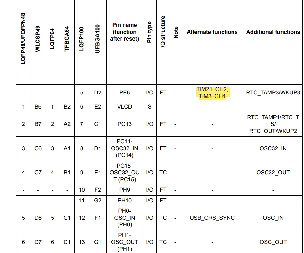
I have found those but when I compare the pin description in the first pic from: NUCLEO-L073RZ | Mbed
with the one provided in this datasheet:Datasheet - STM32L073x8 STM32L073xB STM32L073xZ - Ultra-low-power 32-bit MCU Arm<Sup>®</Sup>-based Cortex<Sup>®</Sup>-M0+, up to 192KB Flash, 20KB SRAM, 6KB EEPROM, LCD, USB, ADC, DACs
I find the pins order is different..

image.pngimage.png

This topic has been closed for replies.
Best answer by Andrew Neil

@Haystak wrote:

I opened the UM1725 file but couldn't find the description for the pins just found the description for Arduino connectors


Table 30, as you showed, describes the Morpho connectors - that's the outer double rows of pins.

For the Arduino pins, see Table 18:
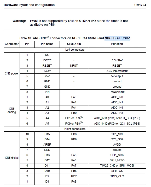
AndrewNeil_1-1713531554720.png

These tell you which of the microcontroller's pins is connected to each pin on those connectors.

Not sure what further "description" of the pins you're looking for?

The names of the pins in these tables are the same names used in the datasheet table you showed initially:
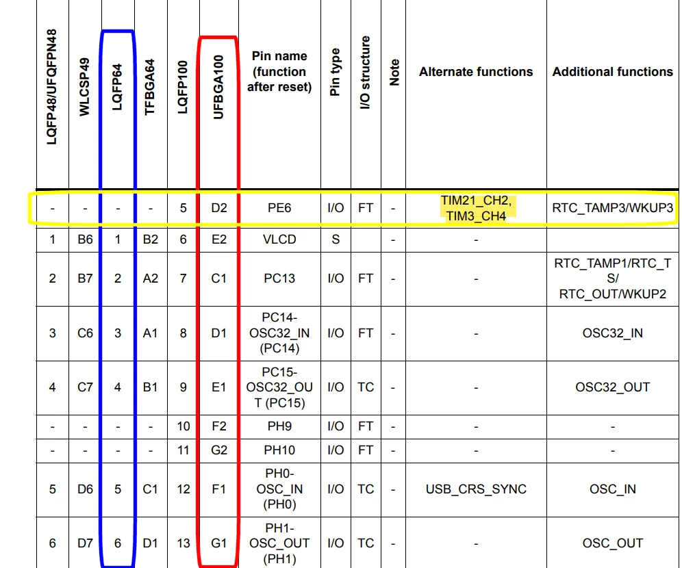
AndrewNeil_3-1713532251755.png


As @STTwo-32 said, the datasheet lists pins for all possible package variants; the ones you highlighted are only available on the UFBGA100 package (Red) - they are not available on the LQFP64  package (Blue) used on the Nucleo board.


EDIT: highlight the different packages


EIDT 2:

In the case of the pin highlighted in yellow:

  • The name of the pin is "PE6" - this is the name that the Nucleo tables refer to
  • The position of the pin on the UFBGA100 package is "D2"
  • The position of the pin on the LQFP100 package is "5"
  • The pin is not present on any of the other packages - including the  LQFP64  package used on the Nucleo board.
  • The pin named "PE6" can be configured for one of the Alternate Functions TIM21_CH2 or TIM3_CH4, or the Additional Functions RTC_TAMP3 or WKUP3

 

4 replies

Andrew Neil
Super User
April 19, 2024

It should be on the 'Documentation' tab of the Product Page - but that does, indeed, seem to be missing:

AndrewNeil_0-1713527071148.png

What you require is the User Manual UM1724

AndrewNeil_1-1713527228787.png


Google finds it OK - so no idea why it's gone from the Product Page!

https://www.st.com/resource/en/user_manual/um1724-stm32-nucleo64-boards-mb1136-stmicroelectronics.pdf


A complex system that works is invariably found to have evolved from a simple system that worked.A complex system designed from scratch never works and cannot be patched up to make it work.
Andrew Neil
Super User
April 19, 2024

No, my Mistake - that was the chip Product Page.

The Product Page for the Nucleo board does have a 'Documentation' tab, and UM1724 is listed:

AndrewNeil_2-1713527533442.png

https://www.st.com/en/evaluation-tools/nucleo-l073rz.html#documentation


Does leave the Question of why the chip page has no 'Documentation' tab, though ...

A complex system that works is invariably found to have evolved from a simple system that worked.A complex system designed from scratch never works and cannot be patched up to make it work.
Andrew Neil
Super User
April 19, 2024

@Andrew Neil wrote:

Does leave the Question of why the chip page has no 'Documentation' tab, though ...


@STTwo-32 - any ideas ?

A complex system that works is invariably found to have evolved from a simple system that worked.A complex system designed from scratch never works and cannot be patched up to make it work.
STTwo-32
ST Technical Moderator
April 19, 2024

Hello @Haystak and welcome to the ST Community :smiling_face_with_smiling_eyes:.

The NUCLEO-L073RZ is based on the package LQFP64 of the STM32L073RZ. So, the available pins are just the Pins on this package. For example, the Pin that you have mentioned in yellow is not available on this MCU. For pins on the Board refer to both MCU's Datasheet and the board User manual.

Best Regards. 

STTwo-32

To give better visibility on the answered topics, please click on Accept as Solution on the reply which solved your issue or answered your question.
Andrew Neil
Super User
April 19, 2024

@Haystak wrote:

I find the pins order is different..


Not sure what you mean by that?

The order in which pins are broken-out to the headers is entirely unrelated to the order of the pins on the chip package.

A complex system that works is invariably found to have evolved from a simple system that worked.A complex system designed from scratch never works and cannot be patched up to make it work.
HaystakAuthor
Associate
April 19, 2024

Thank you for the reply 
I said order but I meaned the function  (sorry for miss clafication) for example here 

I opened the UM1725 file but couldn't find the description for the pins just found the description for Arduino connectors

image.png

STTwo-32
ST Technical Moderator
April 19, 2024

As I told you. To understand the pin description on each connector on the NUCLEO Board, I suggest you follow the User manual and refer to the datasheet of the MCU for description of possible functions on each pin.

Best Regards.

STTwo-32

To give better visibility on the answered topics, please click on Accept as Solution on the reply which solved your issue or answered your question.
Andrew Neil
Super User
April 19, 2024

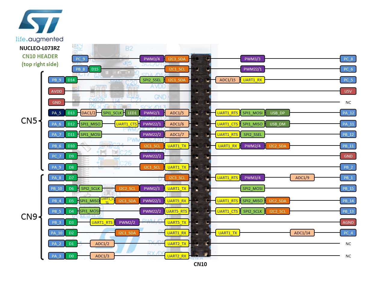
If you want to access the TIM21_CH2 Alternate Function on the Nucleo board, it's also available on PA3 and PB14:

AndrewNeil_0-1713533634467.png

AndrewNeil_1-1713533666230.png


Similarly, the TIM3_CH4 Alternate Function on the Nucleo board is available on PC9 and PB1:

AndrewNeil_2-1713533740118.png


AndrewNeil_3-1713533757772.png


A complex system that works is invariably found to have evolved from a simple system that worked.A complex system designed from scratch never works and cannot be patched up to make it work.