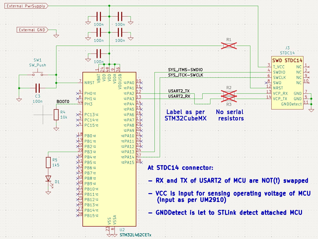
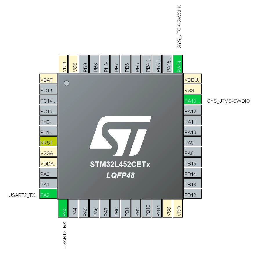
Schematic to connect STLink-V3MINIE to STM32 MCU
Hi,
after starting with Nucleo-L432KC development board I need to switch to a variant with more I/Os, and thus I’m creating a stand-alone development board with STM32L462CET in LQFP48 package.
I purchased a STLink-V3MINIE for programming/debugging but, like others, was confused on how to properly connect the STLink to the MCU. Since various answers are given in lots of threads I summarized in a simplified sketch what I consider as correct.
Please have a look on attached schematic and configuration of MCU done in CubeMX. To keep it as simple as possible I removed everything but the MCU, the STDC14 connector of the V3MINIE and just an LED to apply the minimum blink-example.
Please, focus on the connection of STDC14 connector and BOOT0. I think, with this, it is possible to download the blink-software and run the debugger. Am I correct?
Regards
Sebastian