Isoux
Associate
Oct 1, 2020 10:19 PM UTC
Solved

Programming STM32F103ZET6 or STM32F105VCT6 for the VERY first time (using ST-LINK utility)

I have experience with several types of classic boards with STM32 microcontrollers (NUCLEO, Blue Pill...) that immediately connect with the stlink-v2 and st-info --probe command showing the characteristics of the controller and after that flashing is successful...

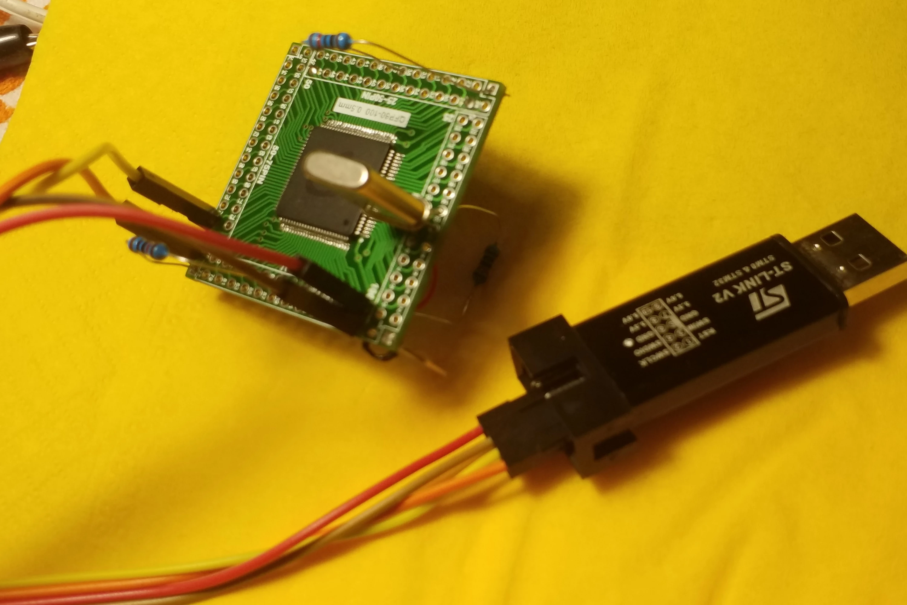
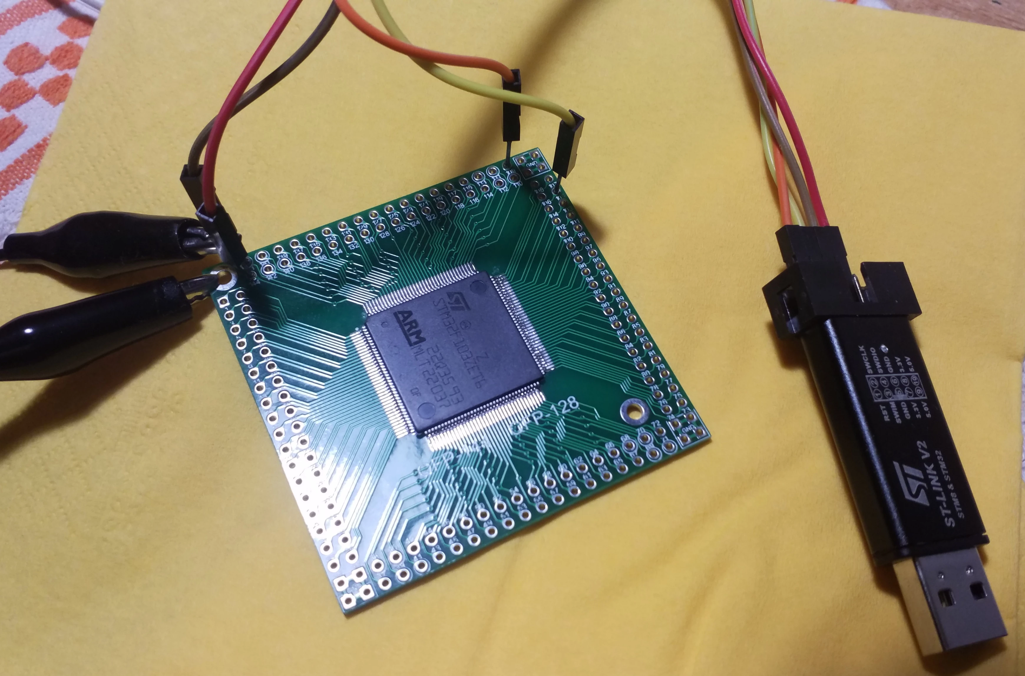
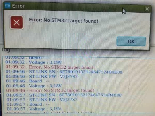
I recently bought the above mentioned two controllers and a boards (LQFP144/100 SMT to DIP Adapter PCB Board) where I soldered them with the necessary capacitors between all the VDD and VSS contacts. I properly connected SWDIO and SWCLK to PA13, PA14 pins, NRST to VDD over 10k resistors even boot0 over 10k resistors to VSS (This is how I noticed on all the schemаtics). There is no way I can read the microcontroller or flash it, although in addition to st-info and st-util, I also used STMCubeProgrammer and a linker on the Linux and Windows systems.

Result:

st-info --probe

Found 1 stlink programmers

 serial:   6e78010132124647524b4e00

 hla-serial: "\x6e\x78\x01\x01\x32\x12\x46\x47\x52\x4b\x4e\x00"

 flash:   0 (pagesize: 0)

 sram:    0

 chipid:   0x0748

On one site I found detailed instructions on how to program the new STM32f103c8t6 for the first time. Nothing special is stated there and I did it all and I don't succeed at all.

I found almost nothing on Google that would help me except for someone to mention somewhere to "Pay special attention to the pull-up resistor on the TDO line", (PB2 ?).

Is there any useful advice or experience?
0693W000004IRZAQA4.jpg0693W000004IRYqQAO.jpg0693W000004IRYRQA4.jpg

This topic has been closed for replies.
Isoux
IsouxBest answer
Associate
Oct 1, 2020 11:37 PM UTC

The problem is solved!

The downside was that I didn’t connect VDDA to VDD because I felt it wasn’t necessary if I didn’t use ADC.

after I connected VDDA to VDD it worked.

16 replies

TDK
Oct 1, 2020 10:41 PM UTC

You should have decoupling capacitors near the chip. You said you soldered them in your post but I don't see them on the boards anywhere. They're supposed to be close to the chip.

Rather than trying to solder this to a breakout board, buying a Nucleo board might be better and more cost efficient.

"If you feel a post has answered your question, please click ""Accept as Solution""."
Isoux
IsouxAuthor
Associate
Oct 1, 2020 10:44 PM UTC

Thanks

They are on the other side... 100nF ...

TDK
Oct 1, 2020 10:46 PM UTC
"If you feel a post has answered your question, please click ""Accept as Solution""."
Isoux
IsouxAuthor
Associate
Oct 1, 2020 10:50 PM UTC

Blue Pill works great with all 100nf decoupling capacitors that's not a problem, I guess it's something else

TDK
Oct 1, 2020 10:57 PM UTC
"If you feel a post has answered your question, please click ""Accept as Solution""."
Isoux
IsouxAuthorBest answer
Associate
Oct 1, 2020 11:37 PM UTC

The problem is solved!

The downside was that I didn’t connect VDDA to VDD because I felt it wasn’t necessary if I didn’t use ADC.

after I connected VDDA to VDD it worked.

Isoux
IsouxAuthor
Associate
Oct 1, 2020 11:42 PM UTC

The problem is solved!

The downside was that I didn’t connect VDDA to VDD because I felt it wasn’t necessary if I didn’t use ADC.

after I connected VDDA to VDD it worked.