

Associate
April 23, 2024
Solved

problem of using USART3 on STMH563ZI

I'm new to STM and I'm trying to use USART to communicate between MCU board and my computer. I'm now using USART2 and CP2102 to translate TTL to USB. And have succeeded. But my goal is to directly use USB-C of STLINK to output serial data, because the user manual of this board just like below shows that the USART3 can directly output to USB-C of STLINK.  But I failed to use only USB to communicate and I don't no why.
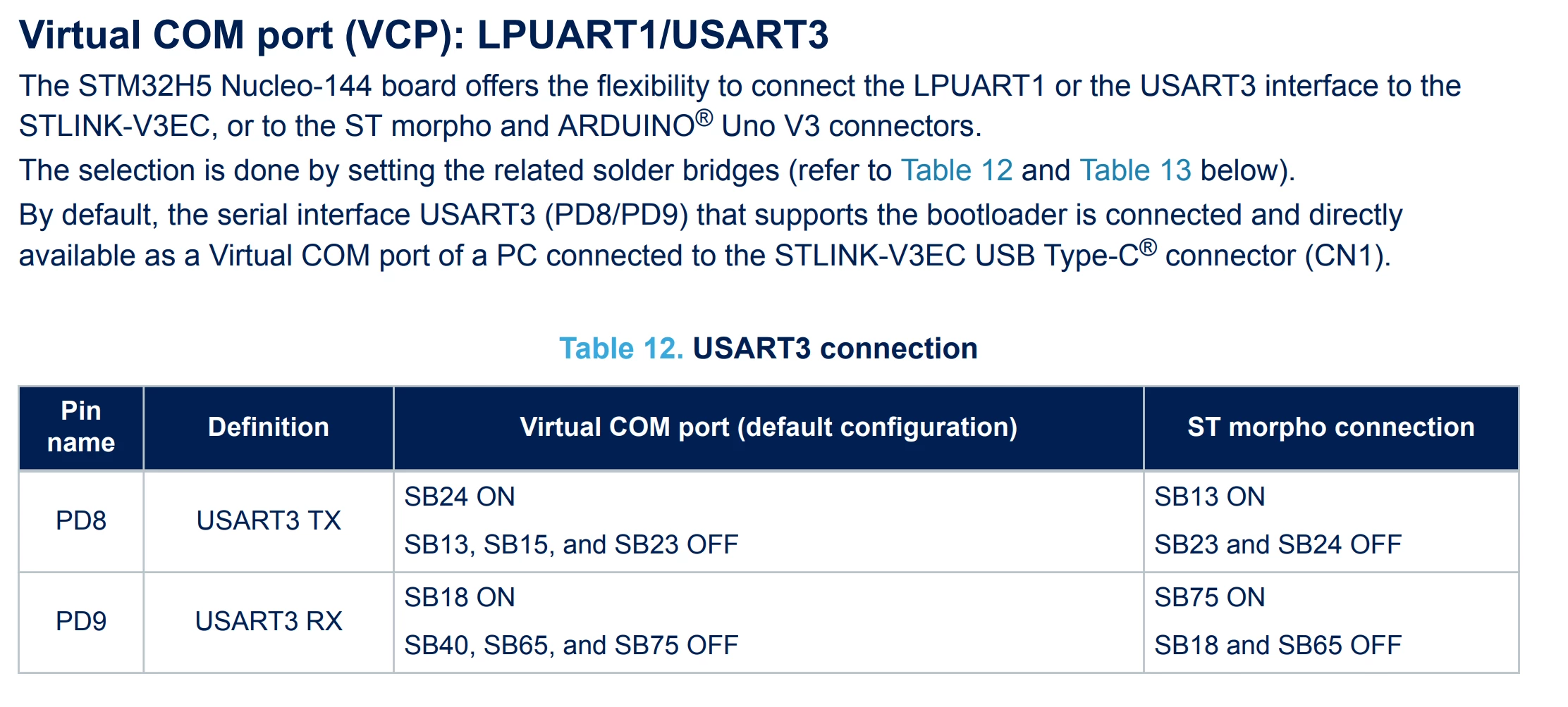
BrianYuan_0-1713880809410.png


This topic has been closed for replies.
mƎALLEm
mƎALLEmBest answer
ST Technical Moderator
April 23, 2024

Hello,

Via ZIO connector, simply connect:

USART2_RX (PA3)  to USART3_TX (PD9)
USART2_TX (PD5) to USART3_TX (PD8)

Without disordering anything, you need to ensure that USART3 IOs are not configured to keep them as inputs.

To give better visibility on the answered topics, please click "Best answer" on the reply which solved your issue or answered your question.

8 replies

Pavel A.
April 23, 2024

Check the solder bridges mentioned in the documentation. Has anyone played with this board before you?

Is the VCP of the board visible on the host side (lsusb or device manager) ?


BrianYuanAuthor
Associate
April 24, 2024

Thanks for your reply.
This board is brand new board, so the solder bridges should be default just like mentioned in the documentation. And sorry that I don't know what is VCP, could you please explain what do you mean by VCP is visible on host side?

Andrew Neil
Super User
April 24, 2024

@BrianYuan wrote:

 what is VCP, could you please explain what do you mean by VCP is visible on host side?


VCP = Virtual COM Port - the USB-to-UART connection appears on the PC as a "virtual" COM port,


@BrianYuan wrote:

 please explain what do you mean by VCP is visible on host side?


When you plug the board in to your host computer, do you see its "COM port" appear?

You haven't said what computer you're using, but on Windows it would appear in Device Manager; eg,

AndrewNeil_0-1713945773813.png


A complex system that works is invariably found to have evolved from a simple system that worked.A complex system designed from scratch never works and cannot be patched up to make it work.
mƎALLEm
mƎALLEmBest answer
ST Technical Moderator
April 23, 2024

Hello,

Via ZIO connector, simply connect:

USART2_RX (PA3)  to USART3_TX (PD9)
USART2_TX (PD5) to USART3_TX (PD8)

Without disordering anything, you need to ensure that USART3 IOs are not configured to keep them as inputs.

To give better visibility on the answered topics, please click "Best answer" on the reply which solved your issue or answered your question.
BrianYuanAuthor
Associate
April 24, 2024

Do you mean that I should set USART3 to disabled. Then output the TX RX from USART2 and connect it to output pin of USART3 (TX to TX RX to RX) than I can read the data from the USB-C of STLINK?

mƎALLEm
ST Technical Moderator
April 24, 2024

Yes and you need to disable the gpio pins of USART3 no matter it’s is enabled or not. 

To give better visibility on the answered topics, please click "Best answer" on the reply which solved your issue or answered your question.
