Associate
Jun 25, 2025 9:47 PM UTC
Solved

Nucleo-G491RE and opamp1

I am using Nucleo-G491RE. I am debugging through the built-in ST-Link using STM32CubeIDE 1.18.1. My design uses opamp1 in standalone mode, which assigns OPAMP1_VOUT to PA2 and OPAMP1_VINM to PA3. What configuration of solder bridges will bring these opamp signals to the Arduino or Morpho connectors?  I have studied the user manual (MB1367) section 6.7, but it is not clear to me.

This topic has been closed for replies.
TDK
TDKBest answer
Jun 25, 2025 9:59 PM UTC

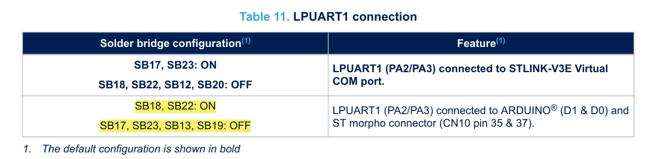
SB18/SB22 on

SB13/SB17/SB19/SB23 off

TDK_1-1750888648506.png


PA2/PA3 are then brought to the headers instead of the default PC4/PC5.

"If you feel a post has answered your question, please click ""Accept as Solution""."

5 replies

TDK
TDKBest answer
Jun 25, 2025 9:59 PM UTC

SB18/SB22 on

SB13/SB17/SB19/SB23 off

TDK_1-1750888648506.png


PA2/PA3 are then brought to the headers instead of the default PC4/PC5.

"If you feel a post has answered your question, please click ""Accept as Solution""."
Andrew Neil
Super User
Jun 25, 2025 10:00 PM UTC

It might be clearer to look at the schematics?


A complex system that works is invariably found to have evolved from a simple system that worked.A complex system designed from scratch never works and cannot be patched up to make it work.
Associate
Jun 26, 2025 12:27 AM UTC
Thank you. Where can I find the schematics? I have looked.
TDK
Jun 26, 2025 12:35 AM UTC
"If you feel a post has answered your question, please click ""Accept as Solution""."