This topic has been closed for replies.
STTwo-32
STTwo-32Best answer
ST Technical Moderator
October 1, 2024

Hello @Karl Yamashita @Andrew Neil 

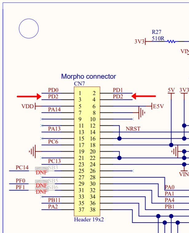
After checking with our HW team, I can confirm that both connectors CN7-3 and CN7-4 are mapped to the same pin of the MCU (PD2).

Best Regards.

STTwo-32

To give better visibility on the answered topics, please click on Accept as Solution on the reply which solved your issue or answered your question.

4 replies

STTwo-32
ST Technical Moderator
October 1, 2024

Hello @Karl Yamashita 

Thank you for this contribution. I'm checking internally and i will be back to you ASAP.

Best Regards.

STTwo-32

To give better visibility on the answered topics, please click on Accept as Solution on the reply which solved your issue or answered your question.
Andrew Neil
Super User
October 1, 2024

Fig 7 in UM2953 is the same:

AndrewNeil_1-1727801087393.png


PS:

PD3 is on CN10.1 both in schematic and in UM2953 Fig 7


A complex system that works is invariably found to have evolved from a simple system that worked.A complex system designed from scratch never works and cannot be patched up to make it work.
STTwo-32
STTwo-32Best answer
ST Technical Moderator
October 1, 2024

Hello @Karl Yamashita @Andrew Neil 

After checking with our HW team, I can confirm that both connectors CN7-3 and CN7-4 are mapped to the same pin of the MCU (PD2).

Best Regards.

STTwo-32

To give better visibility on the answered topics, please click on Accept as Solution on the reply which solved your issue or answered your question.
Karl Yamashita
Principal
October 1, 2024

As @Andrew Neil, PD3 is on CN10, which i missed.

Though it doesn't make sense to have PD3 by itself when it could have been grouped with the other 3 PDx pins. Unless there is a reason to have PD3 on CN10?

If a reply has proven helpful, click on Accept as Solution so that it'll show at top of the post.CAN Jammer an open source CAN bus hacking toolCANableV3 Open Source