Associate
August 4, 2026
Solved

Noisy LVDS on custom DSI driver board (STM32U5G9)

  • August 4, 2026
  • 7 replies
  • 96 views

Hi everyone,

I need some help please on a choppy DSI signal.

Long story short, I have decided to clone an STM32U5G9 disco board and build my own DSI driver using the same mcu in a smaller package running at 3v3 VDD. All seems to be fine, all voltages levels are correct on the screen after removing R8 and bridging R9 (backlight also works) and the VLXSMPS output is the same as on the disco (1.2V). I have signal on all DSI lines as well, as expected.

But...

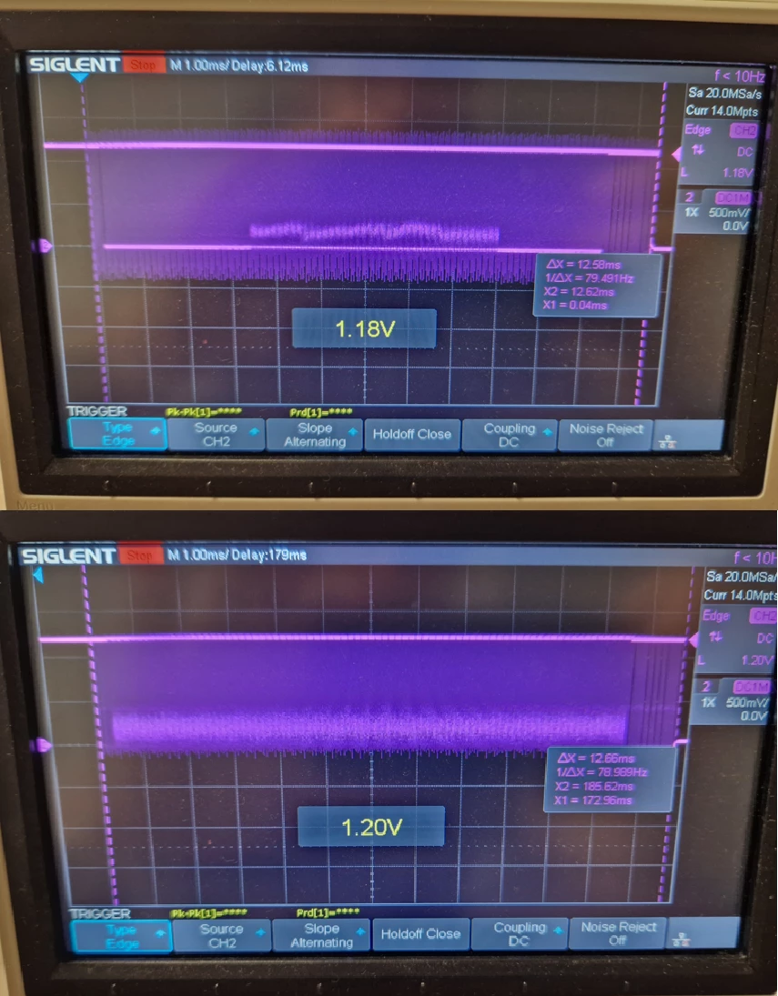
Below I am showing you the DSI_D0N signal from the original disco board, followed by my custom one. The capture was with an oscilloscope on the direct pin output of the two mcu-s, so the screen was not connected in either scenario. It is clear to me that the low state of the signal is too noisy on my custom board and thus, not too surprisingly, I have no output on the screen. Can anyone give me a hint please over what I did wrong in my design?

About the custom board, it is 2-layers, the DSI lines are all matched and no vias were used. The DSI and SMPS part of my schematics is the same as the original disco’s, down to using the same components.

The code is also identical.

Thanks in advance!

BFarkas
 

Best answer by Mike_ST

Hello,

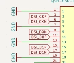
I’m not a DSI expert, and I’m not sure it is the problem, but D0N and D0P are swapped in the schematic.

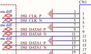
When on the MB1835 board, we have :


There is a function in the HAL that you can call to fix that if this is a problem:

HAL_DSI_SetLanePinsConfiguration(<dsi handle>, DSI_SWAP_LANE_PINS, DSI_DATA_LANE0, ENABLE);

7 replies

MM..1
Super User
August 4, 2026

What you mean "DSI lines are all matched”
And DSI HS is absurd measure 1ms, Real signals is 10ns

BFarkasAuthor
Associate
August 4, 2026

The lines are length matched and are the same 0.15 mm width with 0.2 mm minimum distance between them. The board itself is 2 layers, FR4, 1.55 mm.

The 1 ms measure allowed me to capture the entire first packet on both devices so a direct comparison could be shown between the two.

I am happy to go probe for something else if that would give you a better idea of what is going on.

Thank you.

MM..1
Super User
August 4, 2026

Ok if you mean between pairs 0,2mm then seems ok, but better is show schematics. 

And ofcourse package ?

Mike_ST
Mike_STBest answer
ST Technical Moderator
August 5, 2026

Hello,

I’m not a DSI expert, and I’m not sure it is the problem, but D0N and D0P are swapped in the schematic.

When on the MB1835 board, we have :


There is a function in the HAL that you can call to fix that if this is a problem:

HAL_DSI_SetLanePinsConfiguration(<dsi handle>, DSI_SWAP_LANE_PINS, DSI_DATA_LANE0, ENABLE);

In order to give better visibility on the answered topics, please click on 'Best answer' on the reply which solved your issue or answered your question. 
BFarkasAuthor
Associate
August 5, 2026

Hi Mike,

Your name shall be written in full ENIG on my next PCB!

That was the problem!

Thank you!

Balazs

unsigned_char_array
Lead III
August 5, 2026

please mark the solution as “best answer”.

"Kudo posts if you have the same problem and kudo replies if the solution works.Click ""Accept as Solution"" if a reply solved your problem. If no solution was posted please answer with your own."