Associate
September 5, 2026
Solved

Hardware Discrepancy on NUCLEO-F767ZI: U6 LDO footprint is 8-pin, but schematic shows 6-pin

  • September 5, 2026
  • 10 replies
  • 134 views

Hi everyone,

I am currently working on repairing my NUCLEO-F767ZI board (Revision: [MB1137 Rev B]). The 3.3V LDO regulator (U6) was damaged and needs to be replaced.

While working on it, I found a hardware discrepancy:

  • According to the official schematic, U6 is specified as LD39050PU33R (a 6-pin DFN package).

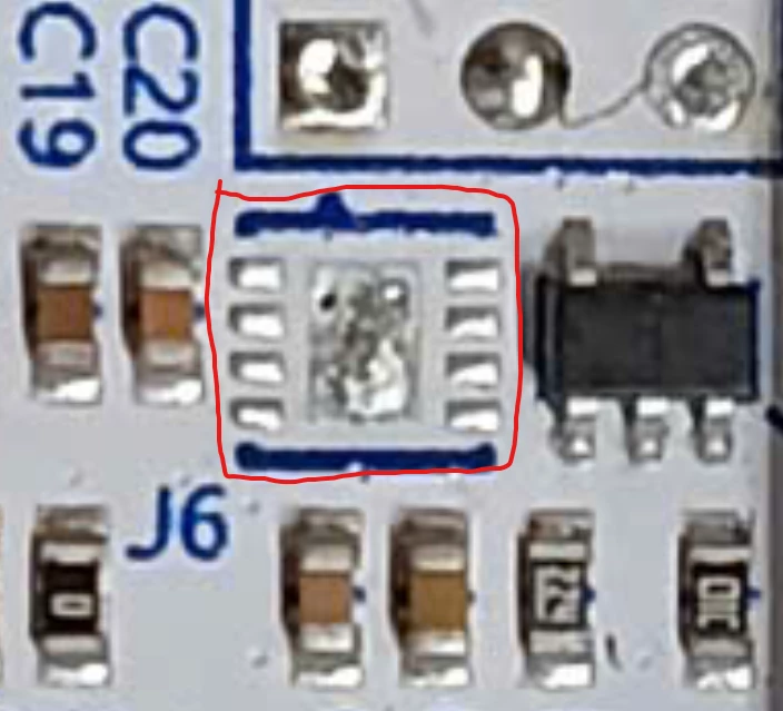
  • However, on my physical board, the PCB footprint for U6 clearly has 8 pads.

  • The damaged original IC I removed is an 8-pin package with the marking code "PH 2kE".

Since a 6-pin IC cannot fit on this 8-pin footprint, has anyone encountered this before? Could you please help me identify the correct 8-pin LDO part number to replace it?

I have attached pictures of the physical 8-pin IC and the 8-pad PCB footprint for reference.

Any advice would be greatly appreciated. Thanks in advance!
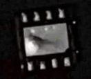
 

Figure 1: The removed original 8-pin LDO IC with the marking code "PH 2kE".
Figure 2: The physical 8-pad PCB footprint for U6 on the NUCLEO-F767ZI board.


Best answer by AScha.3

So check pinout /matching for AP7361C-33FGE-7 : 


https://www.mouser.de/datasheet/3/175/1/AP7361C.pdf


10 replies

Peter BENSCH
ST Technical Moderator
September 6, 2026

Welcome ​@CongTien, to the community!

There are several ways to get support for STMicroelectronics devices:

  1. your local distributor
  2. the public worldwide Community, where users primarily help one another
  3. the personal Online Support OLS

You asked exactly the same question both in the community and to OLS under the ticket number 00268548. However, making the most noise does not necessarily increase the speed at which you receive an answer. I therefore recommend waiting first for a reply from the colleagues at OLS.

Thank you for understanding.

Regards
/Peter

In order to give better visibility on the answered topics, please click on Accept as Solution on the reply which solved your issue or answered your question.
CongTienAuthor
Associate
September 6, 2026

Hi Peter,

Thank you for the clarification, and I sincerely apologize for the duplication. I didn't mean to rush ST's support team at all. I simply wanted to reach out to both the official staff through OLS and perhaps connect with community members who might have encountered this exact hardware discrepancy before.

I will wait patiently for the response on my OLS ticket (00268548). Thank you for your time.

Best regards,

AScha.3
Super User
September 6, 2026

Hi,

so your 3v3 LDO is probably LD39200DPU33R .

https://www.st.com/resource/en/datasheet/ld39200.pdf

in DFN8 package.

Check the connections in -- out on your board, from solder pads :  pin 7-8 connects to 5V on board ?

if pin 1-2-3 connected, = LD39200DPU33R ; connects to 3v3 on board ?

If you feel a post has answered your question, please click on " Best Answer ".
CongTienAuthor
Associate
September 6, 2026

Hi A Scha.3,

Thank you for the suggestion! I checked the board layout and performed some continuity tests based on your description, but here is what I found:

  • Only one pin on the top-left (as shown in Figure 2) is connected to 3.3V (instead of pins 1-2-3).

  • The two pins connected to 5V are located at the top and bottom rather than adjacent pins (like pins 7-8 in the datasheet).

Since these results don't seem to match the standard LD39200 DFN8 layout, are there any other specific measurements or tests you would recommend I perform to help identify the correct IC?

Thanks again for your help!

AScha.3
AScha.3Best answer
Super User
September 6, 2026

So check pinout /matching for AP7361C-33FGE-7 : 


https://www.mouser.de/datasheet/3/175/1/AP7361C.pdf


If you feel a post has answered your question, please click on " Best Answer ".
CongTienAuthor
Associate
September 7, 2026

I just checked pin 4 (bottom-left in Figure 2), and it is indeed connected to GND.

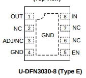
Also, following your lead on Diodes Inc., I found that the older AP7361-33 actually uses the "PH" marking code! Since both the AP7361 and the AP7361C share the same package type (U-DFN3030-8 Type E) and pinout, would either of them be a good replacement?
Thanks again!
https://datasheet.octopart.com/AP7361-15FGE-7-Diodes-Inc.-datasheet-12540156.pdf

Kelvintavarez
Visitor II
September 7, 2026

Good find on the PH marking. I would still compare the electrical specifications before treating the AP7361-33 and AP7361C-33 as direct drop-in replacements.

The original AP7361-33 and the AP7361C family are both available in the U-DFN3030-8 package, and the pin functions appear compatible. However, the AP7361C has some changed specifications, including output accuracy, dropout characteristics, quiescent current, and current-limit behavior.

So if the application is not especially sensitive to those differences, the AP7361C-33 may be a suitable replacement, but I would verify the input voltage, EN behavior, output capacitor requirements, load current, and thermal conditions against the original circuit first.

The AP7361 datasheet also identifies the older AP7361 as NRND and points to the AP7361C as the newer device, which makes the C version worth considering for a replacement.

I'd be interested to know whether anyone has actually tested the AP7361C-33 as a drop-in replacement on this particular board.

passaicemergencyroof.com
CongTienAuthor
Associate
October 6, 2026

Hi everyone,

Sorry for the delayed update. I successfully replaced U6 with the AP7361C-33FGE-7.

STM32CubeProgrammer now recognizes the MCU perfectly, confirming that the 3.3V line is stable and the AP7361C-33 is indeed a perfect drop-in replacement for this board.

Thanks again to @A Scha.3 and @Kelvintavarez for your great support!