Visitor II
Oct 9, 2026 8:33 PM UTC
Solved

HAL_RCC_OscConfig timeout on F411E-Disco board

Hi,

I am using the following codes to do system clock initialization on my STM32F411E-Discovery board: 

  /** Initializes the RCC Oscillators according to the specified parameters
* in the RCC_OscInitTypeDef structure.
*/
RCC_OscInitStruct.OscillatorType = RCC_OSCILLATORTYPE_HSE;
RCC_OscInitStruct.HSEState = RCC_HSE_ON; //Use X2 Crystal
RCC_OscInitStruct.PLL.PLLState = RCC_PLL_ON;
RCC_OscInitStruct.PLL.PLLSource = RCC_PLLSOURCE_HSE;
RCC_OscInitStruct.PLL.PLLM = 4;
RCC_OscInitStruct.PLL.PLLN = 192;
RCC_OscInitStruct.PLL.PLLP = RCC_PLLP_DIV4;
RCC_OscInitStruct.PLL.PLLQ = 8;
if (HAL_RCC_OscConfig(&RCC_OscInitStruct) != HAL_OK)


But  

if (HAL_RCC_OscConfig(&RCC_OscInitStruct) != HAL_OK)

returns time out error.

I am sure crystal X2 is connected, but I don’t understand why it gives me time our error.


Previosuly I also tried:

RCC_OscInitStruct.HSEState = RCC_HSE_BYPASS;

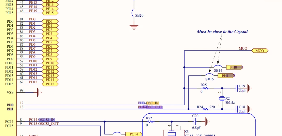
that also threw time out error, I gave up this configuration because I am not sure if SB14 and SB16 are bridged


Here is also the related F411E-Disco board schematic diagram:
 

rich.g.williams
rich.g.williamsBest answer
Senior
Oct 10, 2026 12:24 AM UTC

I would suggest checking a few things:

a) Is HSE actually starting? As a test you can also temporarily configure the PLL to use the internal HSI oscillator instead of HSE, to establish whether the PLL can lock independently of HSE. Allow for HSI not being the same frequency as your HSE.

b) Are your PLL settings valid for the STM32F411?  A multiplier of 192 is a bit high but other PLL settings can prevent lock, so check the PLL input frequency is within range, dividers, multiplier, VCO frequency and resulting clock outputs all OK against the datasheet if you can. Also use ST STM32CubeMX clock configuration diagram, it is really useful for checking if your proposed settings are allowed (if not allowed a setting shows red).

c) For PLL only, HAL is checking - the final instruction, which waits for the PLL ready flag. That final flag will not get set if the settings are not in their allowed ranges (the PLL may start but stall).

If using HSI as a test input the PLL runs that’s good. You can then look to establish whether `HSERDY` ever becomes ready (if HSE is running and becomes ready).  Just as explanation the PLL is like a bell being hit, it rings and settles and then, once running and settled, hardware sets a PLL OK flag.

A note on HSI, HSE and bypass: HSI is the MCU's internal RC oscillator. HSE uses the external high-speed oscillator circuit normally with a crystal connected to the HSE pins. Setting `RCC_HSE_BYPASS` disables the MCU's crystal oscillator amplifier and expects an externally generated clock signal instead; it does not select HSI.

ST STM32CubeMX clock configuration diagram will help you to see the switching settings between HSE HSI and so on and you can write them in HAL.

Bill's Notes

1 reply

rich.g.williams
rich.g.williamsBest answer
Senior
Oct 10, 2026 12:24 AM UTC

I would suggest checking a few things:

a) Is HSE actually starting? As a test you can also temporarily configure the PLL to use the internal HSI oscillator instead of HSE, to establish whether the PLL can lock independently of HSE. Allow for HSI not being the same frequency as your HSE.

b) Are your PLL settings valid for the STM32F411?  A multiplier of 192 is a bit high but other PLL settings can prevent lock, so check the PLL input frequency is within range, dividers, multiplier, VCO frequency and resulting clock outputs all OK against the datasheet if you can. Also use ST STM32CubeMX clock configuration diagram, it is really useful for checking if your proposed settings are allowed (if not allowed a setting shows red).

c) For PLL only, HAL is checking - the final instruction, which waits for the PLL ready flag. That final flag will not get set if the settings are not in their allowed ranges (the PLL may start but stall).

If using HSI as a test input the PLL runs that’s good. You can then look to establish whether `HSERDY` ever becomes ready (if HSE is running and becomes ready).  Just as explanation the PLL is like a bell being hit, it rings and settles and then, once running and settled, hardware sets a PLL OK flag.

A note on HSI, HSE and bypass: HSI is the MCU's internal RC oscillator. HSE uses the external high-speed oscillator circuit normally with a crystal connected to the HSE pins. Setting `RCC_HSE_BYPASS` disables the MCU's crystal oscillator amplifier and expects an externally generated clock signal instead; it does not select HSI.

ST STM32CubeMX clock configuration diagram will help you to see the switching settings between HSE HSI and so on and you can write them in HAL.

Bill's Notes