


Alexey M
Associate
January 5, 2023
Solved

Explain how part of the circuit works with operation amplifier on board B-G431B-ESC1

  • January 5, 2023
  • 2 replies
  • 1965 views

Hello.

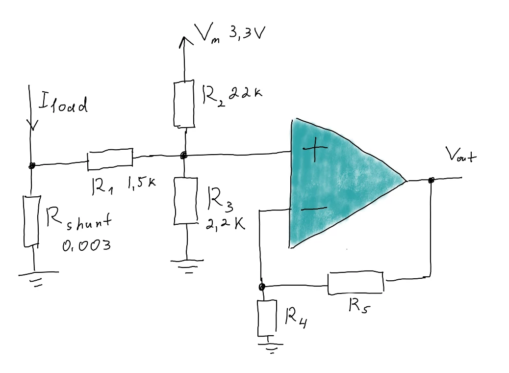
I will try undestand how work plate 'B-G431B-ESC1', more precisely schema operational amplifier (on image).

I have not understood, what does resistors R1, R2, R3 need on cicuit with getting current from shunt? What is the idea behind their work? And the formula for calculating the final gain?
0693W00000Y7WPcQAN.png 

With resistors R5, R6 it is clear - they are internal and are selected when configuring the microcontroller for a fixed gain value (PGA).

I would be very grateful for clarification!
This topic has been closed for replies.
Best answer by Alexey M

Thank you!!

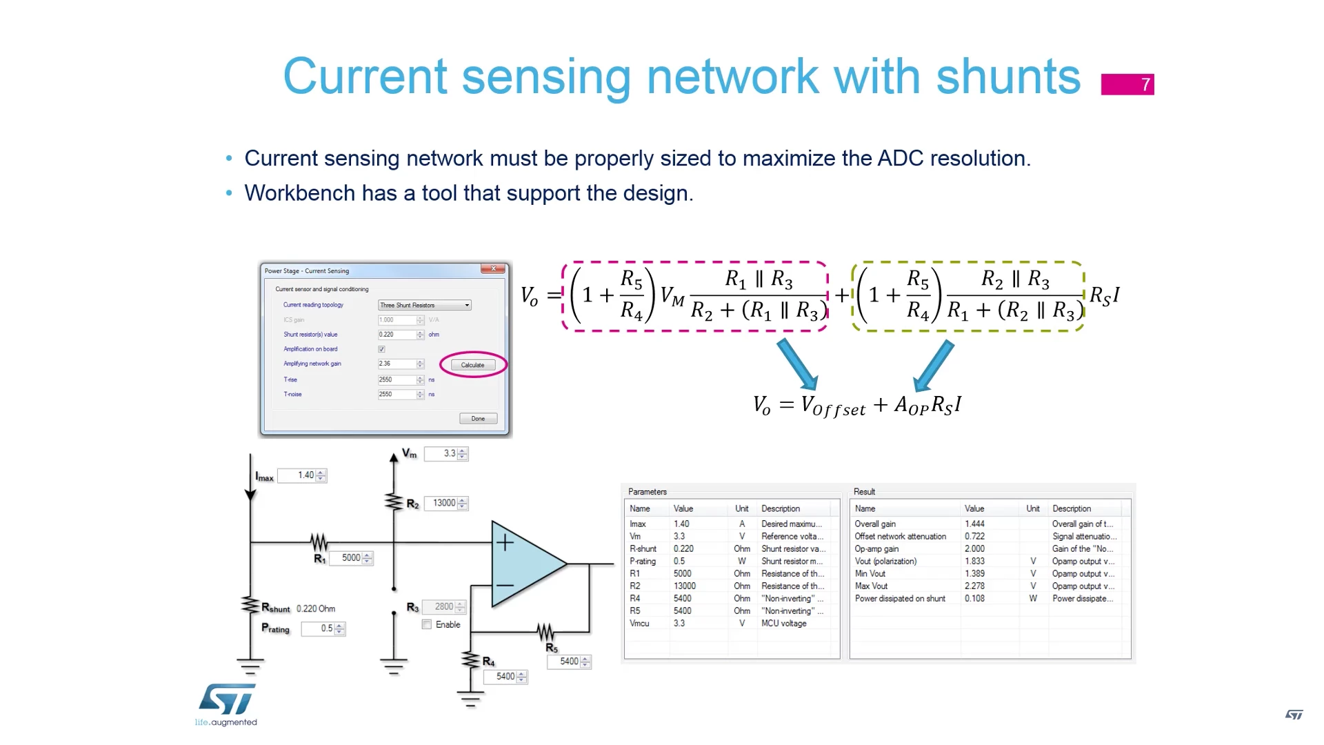
I also, found course about motor from ST about this topic.

Link: https://www.youtube.com/watch?v=dt6bGpykerE

0693W00000Y87NJQAZ.pngPut here, suddenly it will be useful

2 replies

KnarfB
Super User
January 6, 2023

R2, R3 is a voltage divider which is biased by the voltage at Rshunt via R1. The idea is to offset the voltage at Rload into positive range even when Iload is zero or negative. Haven't done the calculations, but it should be straightforward to setup a LTSpice simulation of the input network (or doing the math by hand).

The internal R4 R5 gain can be programmed, you can generate a MotorControl Workbench project and study their settings.

hth

KnarfB

Alexey M
Alexey MAuthorBest answer
Associate
January 12, 2023

Thank you!!

I also, found course about motor from ST about this topic.

Link: https://www.youtube.com/watch?v=dt6bGpykerE

0693W00000Y87NJQAZ.pngPut here, suddenly it will be useful