
Solved
Error with ST-LINK USB debugger and custom board
Hello,
i created a custom board which foundamental schematic is like the images:
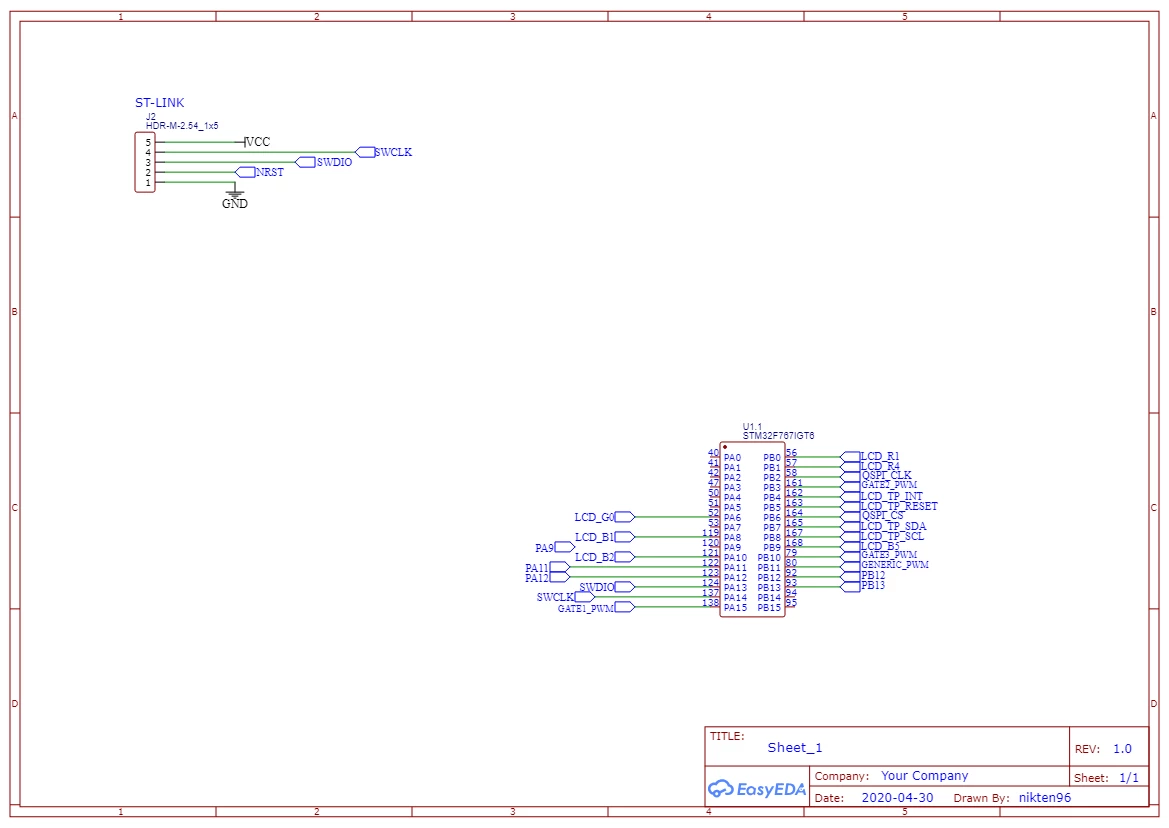
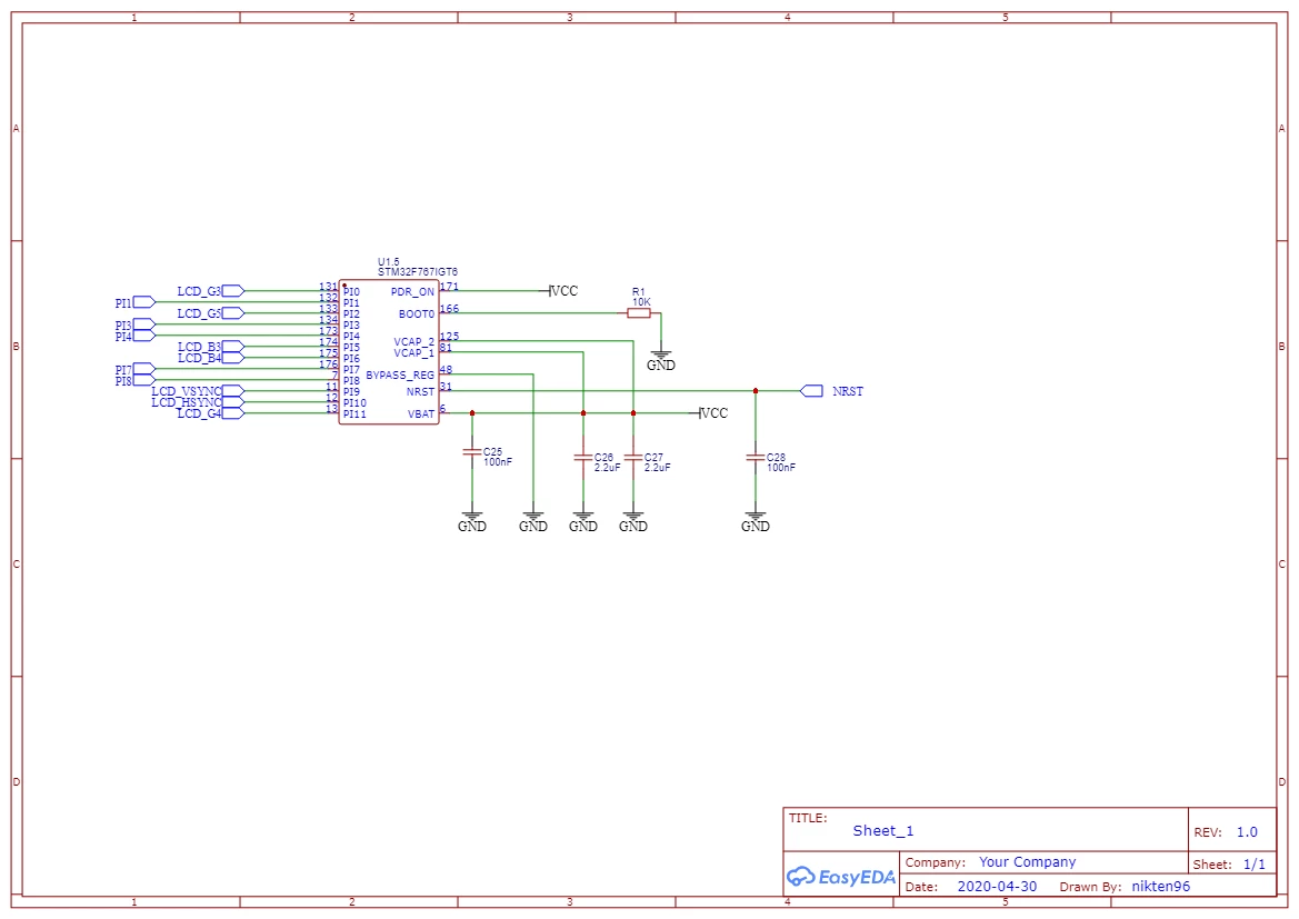
I'm using the classic ST-LINK USB Debugger but i can't debut nor upload my code inside my STM32F767IGT MCU, both with STM32CubeIDE and STM32 ST-Link UTILITY.
In the utility the error was
19:34:31 : Can not connect to target!
 Please select "Connect Under Reset" mode from Target->Settings menu and try again.
 If you're trying to connect to a low frequency application , please select a lower SWD Frequency mode from Target->Settings menu.
19:34:32 : No target connected
or
19:33:54 : Can not connect to target!
 If you're trying to connect to an STM32W1xx device, please select Normal or HotPlug mode from Target->Settings menu.
 If you're trying to connect to a low frequency application , please select a lower SWD Frequency mode from Target->Settings menu.
19:33:55 : No target connected
while in STM32CubeIDE
Error in initializing ST-LINK device.
Reason: Unknown. Please check power and cabling to target.
or
Error in initializing ST-LINK device.
Reason: ST-LINK: 51FF6B064883535241202187 not found.
or
Error in initializing ST-LINK device.
Reason: No device found on target.
What should i do to keep my custom board work?