
Associate
April 13, 2025
Solved

Bootloader via USART1 on NUCLEO-WL55JC1 Nucleo-64 board (MB1389)

  • April 13, 2025
  • 2 replies
  • 534 views

I'm trying program FLASH via serial bootloader using  STM32WL55 USART1 

The an2606 indicates that

  • USART-RX is PA10 pin, connected to CN7-32
  • USART-TX is PA9 pin, connected to CN10-19

I connected the BOOT0 pin to 3.3V

  • If after reset I send 0x7f to LPUART via ST-LINK VCOMM I get ACK (0x79) back
  • But if after reset I send 0x7F to PA10 using external FTDI232 adapter I'm not getting anything back.  If I check level of PA9 it shows 200mV (the PA10 is 3.3V) with FTDI connected and 0V with FTDI disconnected
  • The loopback test on FTDI is working fine, so I don't suspect FTDI malfunctioning

I suspect my board is not properly configured, but could not see anything that would affect PA9 and PA10 configuration. 

Can it be an error in a board documentation, I already spotted one error in table 18, it shows both CN10-35 and CN1-37 connected to PB6, which is probably wrong, one of them must be PB7.



This topic has been closed for replies.
Best answer by Mike_ST

Hello,

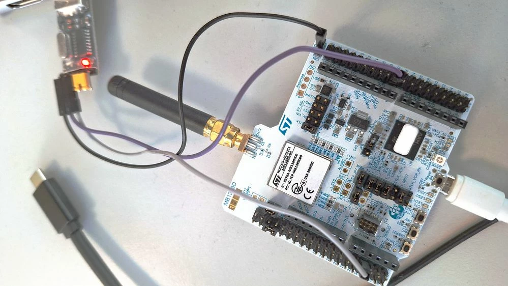
I can confirm the bootloader is working on PA9/PA10,

Here is my setup so you can compare with yours:

Uart1_PA9_PA10.jpg


>> I already spotted one error in table 18

Thank you for reporting. Internal ticket : #207502

2 replies

Mike_ST
Mike_STBest answer
ST Technical Moderator
April 14, 2025

Hello,

I can confirm the bootloader is working on PA9/PA10,

Here is my setup so you can compare with yours:

Uart1_PA9_PA10.jpg


>> I already spotted one error in table 18

Thank you for reporting. Internal ticket : #207502

In order to give better visibility on the answered topics, please click on 'Best answer' on the reply which solved your issue or answered your question. 
Associate
April 14, 2025

Thanks a lot Mike, I don't know what I was doing wrong. I just disassembled my setup and done it again to copy your photo 1:1. That made a trick!