


STM32H5: How to interconnect RCC clocks to timers
Introduction
RCC clocks can be internally connected to timers.
The points addressed here are the following:
- Finding which clock is connected to which timer.
- Finding how the clock is connected to a timer.
- Implementing this connection in STM32CubeMX.
This article focuses on the example of the LSE clock and is based on the example of the STM32H563.
Note: this article is based on RM0481 revision 3.
1. Finding which clock is connected to which timer
The first step is to find the interconnect information in the reference manual (RM). In the case of the STM32H563, it is given in the shape of a peripherals interconnect matrix. Section 15 of the RM0481 describes this.

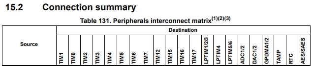



In this table, we can find the following connection information:
- Only TIM2, TIM12, TIM15, TIM16, and TIM17 are concerned by RCC clocks connection.
- In particular, the LSE can be connected to TIM2, TIM15, TIM16.
2. Finding how the clock is connected to a timer
The number in the table refers to the next subsection which gives more details about this peripheral connection. In this case, it is section 15.3.5.
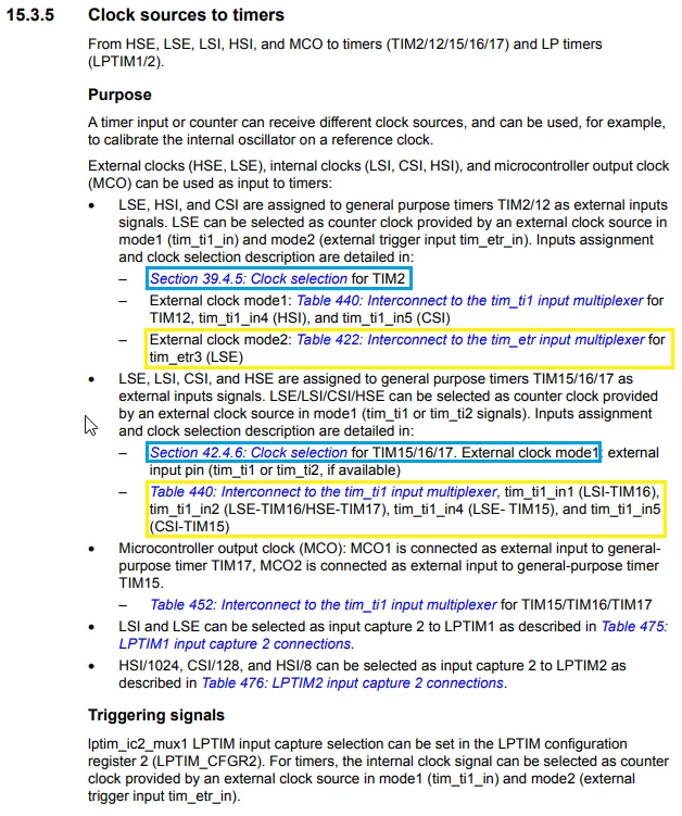
TIM2
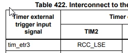
For TIM2, Table 422 shows that LSE is connected to an external trigger signal tim_etr3.
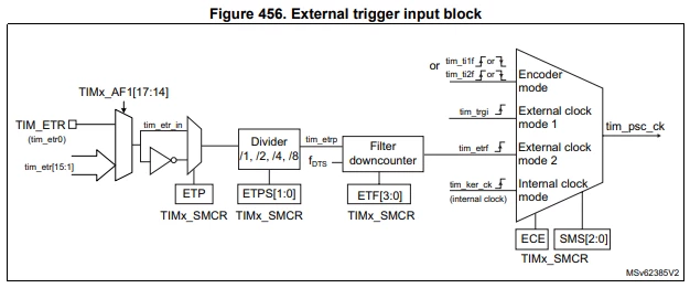
In Section 39.4.5, subsection External clock source mode 2 gives more details and a diagram of the input block.
TIM15/16
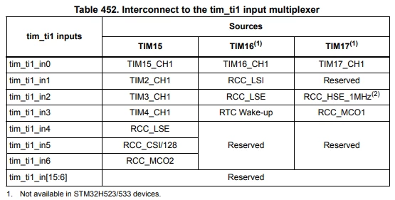
For TIM15/16, Table 452 (Table 440 is a typo error RM0481 revision 3) shows that LSE is connected to an input signal of the timer tim_ti1_in4 of TIM15 or tim_ti_in2 of TIM16.
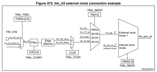
Section 42.4.6, subsection External clock source mode 1 provides more details and a diagram of the input block.
Note:
- The external clock mode 2 is available on TIM2 but not on TIM15/16.
- In external clock mode 2, the clock signal can be divided by 2, 4 or 8. This allows the input to receive a clock with a frequency higher than the tim_ker_ck if it is divided.
- In external clock mode 1, the timer counter can be updated on both edges of the external clock signal. This is not possible when the external clock source mode 2 is used.
3. Implementing this connection in STM32CubeMX
TIM2
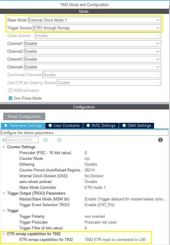
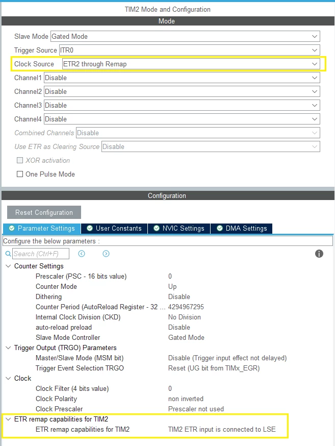
External clock mode 2 can be selected either as the trigger source of a slave mode or directly as a clock source.
When LSE is a trigger source, the slave mode can be any of the possible modes. The screenshot below shows the example of [External Clock Mode 1]. The trigger source is [ETR1 through Remap].
When LSE is a clock source, the slave mode can be disabled or any mode except [External Clock Mode 1]. The clock source is [ETR2 through Remap].
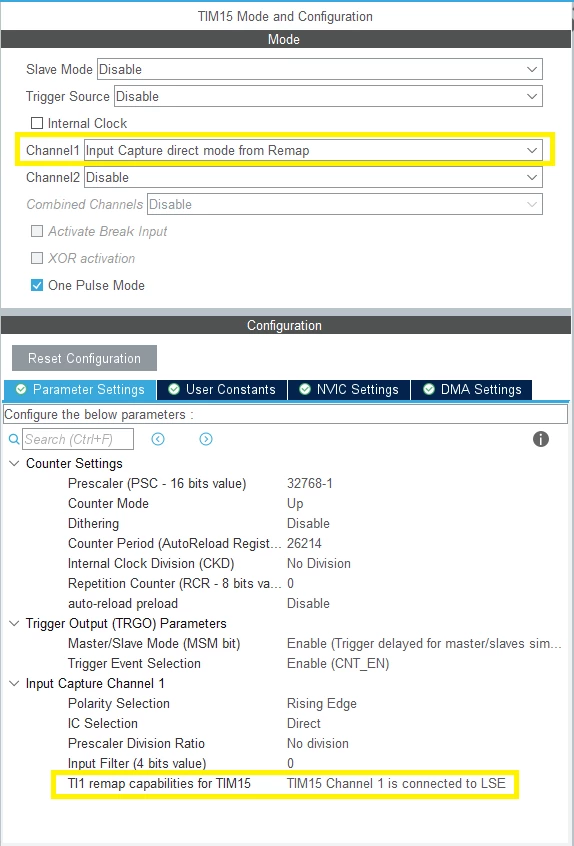
TIM15
The external clock mode 1 is selected on the channel 1 as [Input Capture direct mode from Remap].
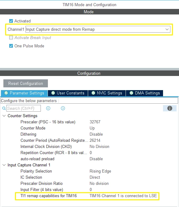
TIM16
The external clock mode 1 is selected on the channel 1 as [Input Capture direct mode from Remap].
Related links
- Reference manual 0481: STM32H523/33xx, STM32H562/63xx, and STM32H573xx Arm®-based 32-bit MCUs
- AN4013: Introduction to timers for STM32 MCUs
- AN4776: General-purpose timer cookbook for STM32 microcontrollers
Specifically, section 2. Timer clocking using external clock-source