
Part 1: How to create a ThreadX low power project from scratch
- 0 replies
- 9627 views
This is part 1 of an article. To read part 2 click here.
Summary
1. The basics
1.1 ThreadX Basics
In case you are new to Microsoft’s Azure RTOS or you need a review of basic RTOS concepts/synchronization primitives, you can review: Introduction to ThreadX [4].
1.2 Hardware requirements
Minimum hardware requirements:
- NUCLEO-U575ZI-Q
- Micro USB Cable
- PC
Optional hardware:
- STLINK-V3PWR + USB Type-C® Cable
At minimum, this demo requires a Nucleo-U575 + a micro-USB cable for connections between the evaluation board and the PC. If you have the standalone STLINK-V3PWR, you can skip the micro-USB cable, but the STLINK V3PWR requires a USB Type-C® connection (see UM3097).
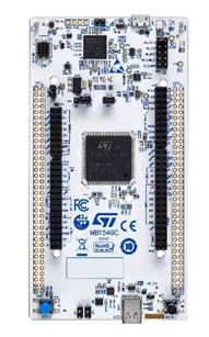 NUCLEO-U575ZI-Q
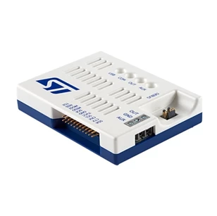 STLINK-V3PWR (optional)
 Micro USB Cable
1.3 Software requirements
Minimum software requirements:
Optional software:
- STM32CubeMonitor-Power (used revision 1.2.1) link [7]
1.4 Program details
Main application thread:
- Try to acquire the 'tx_app_semaphore' immediately.
- On success, toggle the green LED each 500ms for 5 seconds.
- Repeat the above steps.
The tx_app_semaphore is released each time a user presses the user button. This is done in the EXTI ISR callback for the blue user button.
Expected success behavior:
- Green LED toggles every 500ms for 5 seconds each time a user press the user button.
Expected error behavior:
- Red LED toggles every 1 second if any error occurs.
2. Generating your ioc file using STM32CubeMX
2.1 Select your board
Open STM32CubeMX and click the “ACCESS TO BOARD SELECTOR.” Select Nucleo-U575 board as shown in figure 1. You encounter a popup asking whether to initialize the peripherals to their default state; hit yes. Since the STM32U5 is TrustZone® capable MCU, you encounter a second popup asking whether you would like TrustZone® activated; select “without TrustZone® activated.” We are not working with the TrustZone® security feature active for this example.
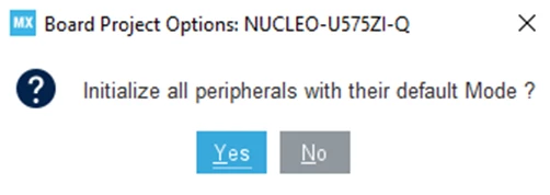 Popup 1: First popup after you select your board.
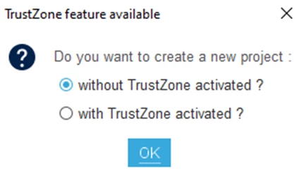 Popup 2: Second popup specific to TrustZone capable MCU.
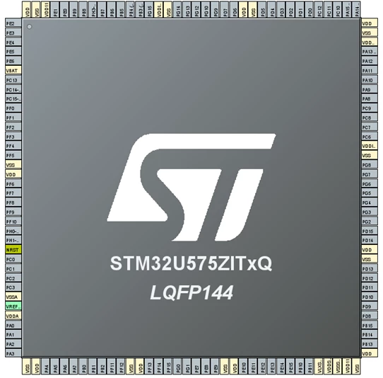 Figure 1: Empty STM32CubeMX ioc project for the STM32U575 MCU. Follow figure 2 to get the clean slate shown here.
You can have all the pinouts unconfigured by following figure 2 (Pinout -> Clear Pinouts).
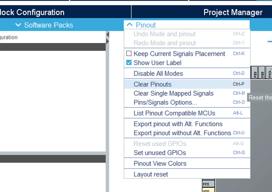 Figure 2: Clear default pinout settings to get the clean slate shown in figure 1.
2.2 Configure ThreadX RTOS
Next, navigate to THREADX RTOS middleware like shown in figure 3 (under the “Middleware and Software Packs” tab).
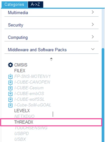 Figure 3: Click THREADX under Middleware and Software packs.
Checkmark the core services (to activate the ThreadX) and low power support as shown in figure 4.
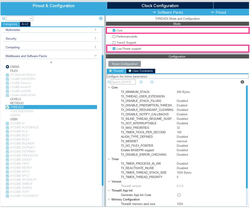 Figure 4: Enable core THREADX services and enable the low power support.
Like figure 5, check “generate app init code” to generate the application ThreadX initialization code inside the “App_ThreadX_Init(VOID *memory_ptr)” function def. Inside this function, you allocate static memory for the main thread (3*1024), create the main thread itself, and finally create the binary semaphore (initialized to 0).
In addition, we enable the low power support to create the required “macros” for handling the low power setup of the MCU hardware when entering and exiting low power mode. This means that the functions are simply declared without any definitions so it would be up to developers to define the hardware config when enter/exit low power mode.
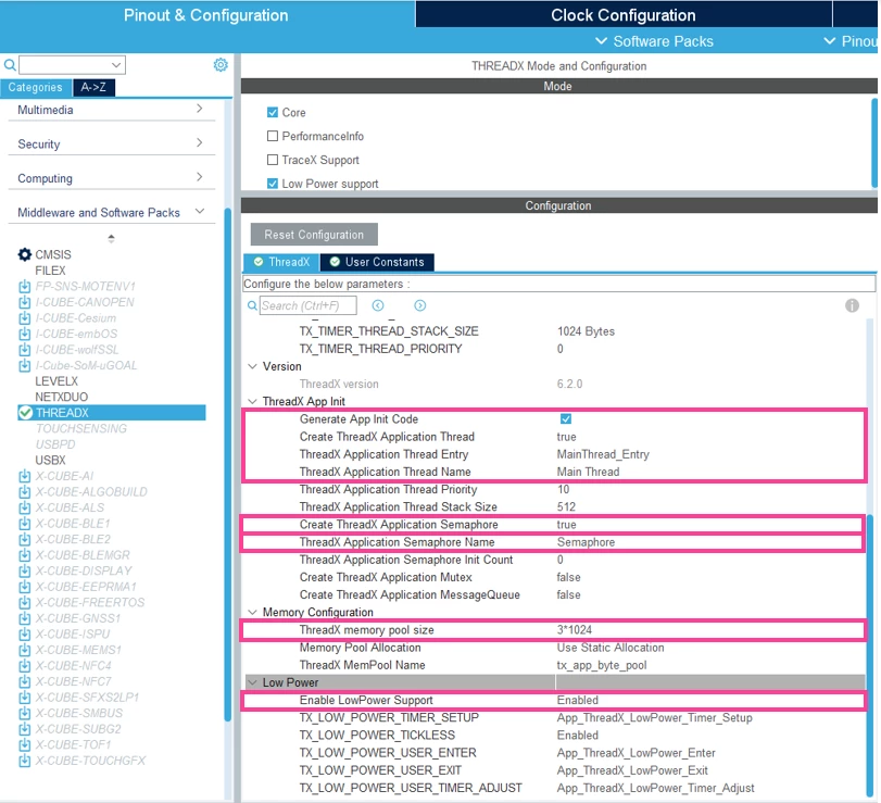 Figure 5: Enable and generate code for core THREADX services like semaphore, configure THREADX memory pool, enable low power support.
We utilize the blue user button of the Nucleo evaluation board for waking up the MCU from low power mode. Since the blue user button is mapped to PC13 (see schematic [ ]), we must configure GPIO pin PC13 as an EXTI pin. The EXTI peripheral helps detect the button being pressed from the GPIO line and generate an interrupt/wakeup-events.
2.3 Configure GPIO peripheral
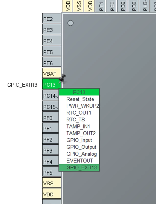 Figure 6: Setup pin PC13 as an externa/extended interrupt input pin, which is internally mapped to the blue user push button, as shown in the schematic of the Nucleo board.
Enable the associated interrupt in the GPIO NVIC for PC13 (figure 7).
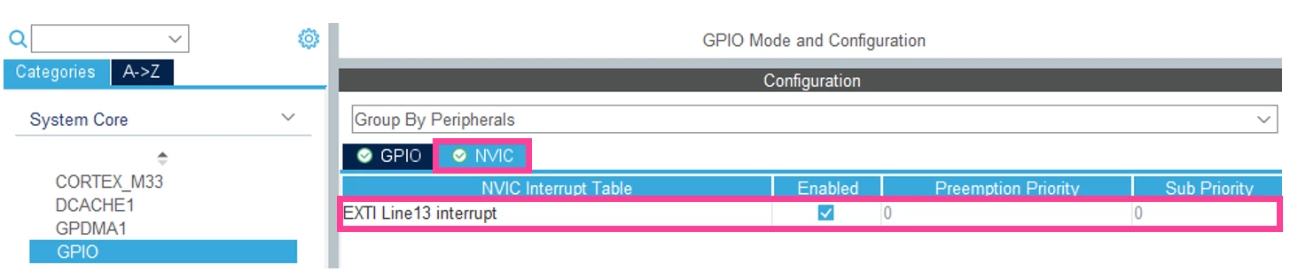 Figure 7: Enable extended/external interrupt line 13 for the blue user button pressing interrupt detection.
Next, we configure two additional GPIO pins as output to two different LEDs to help us track our program status. Pin PC7 is configured as the output and it also physically mapped to the green LED1 on the Nucleo board as shown in [1].
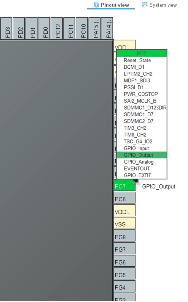 Figure 8: PC7 configured as output pin and is also mapped to the user LED1 on the Nucleo board, as shown in the schematic of Nucleo board.
Pin PG2 is physically mapped to the red LED3 on the Nucleo board as shown in schematic [1].
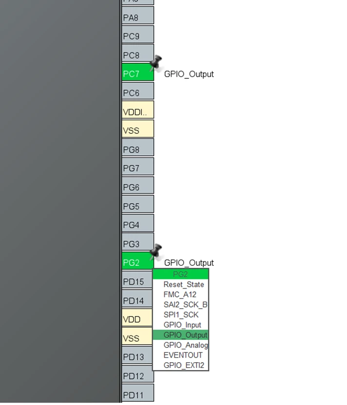 Figure 9: PG2 configured as output pin and is also mapped to the user LED2 on the Nucleo board, as shown in the schematic of Nucleo board.
Figure 10 below is just for your reference, and nothing needs to be changed.
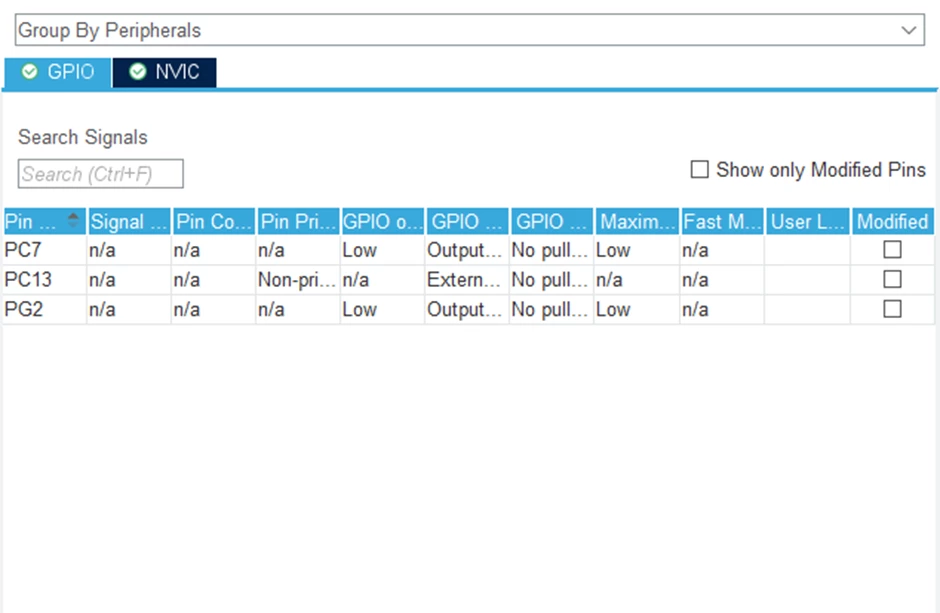 Figure 10: Overview of all the GPIO pins we configured. “System Core” -> “GPIO”.
2.4 Configure PWR mode
Looking at figure 12, to save additional power, disable all the peripherals that you will not use. For instance, we leave SRAM2 page 1 (0x20030000) with full retention during stop mode because that is where some of our data code is stored. We do not need other RAM pages, so we disable retention (content is lost during stop mode) for those; see figure 11. To access the “memory details” like shown in figure 11, click on “build analyzer” in the bottom right side of the STM32CubeIDE window (if not shown, click “window” -> “show view” -> “build analyzer”).
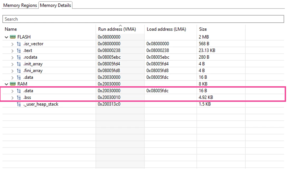 Figure 11: STM32CubeIDE Build Analyzer feature: initialized data segment (“.data”) and initialized data segment (“.bss”) is stored in SRAM2 page 1 (“RAM”).
In figure 12, similarly, I-cache is kept with full page retention because our code instruction utilizes it for performance reasons. Refer to the STM32U575 reference manual [2] “PWR power management” section for full details about the power modes and the low power features. Specifically, refer to stop 2 mode power saving features.
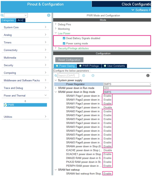 Figure 12: Power down unused memory area (“Enable”).
2.5 Configure instruction cache
Enable I-cache as shown in figure 13 below for performance reasons.
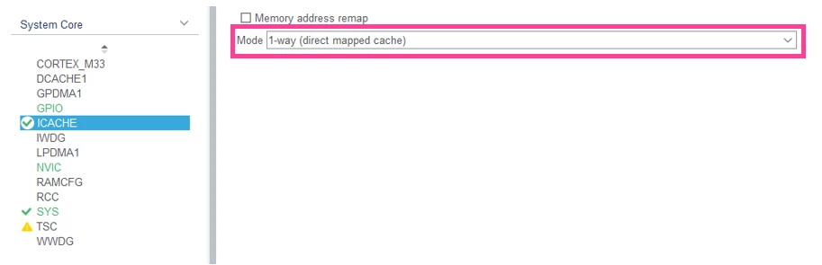 Figure 13: Enable ICACHE for performance reasons.
2.6 Configure HAL Timebase
Select one of the timers for HAL time base since ThreadX RTOS already uses the Systick timer for its services. We selected timer 6 because it is one of the basic timers that is good enough for our purpose.
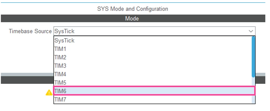 Figure 14: SYSTICK is reserved for RTOS. HAL time base is switched to one of the timers, like TIM6.
Enable EXTI interrupt used for generating interrupt for waking up MCU after the blue user button is pushed.
2.7 NVIC timer configuration
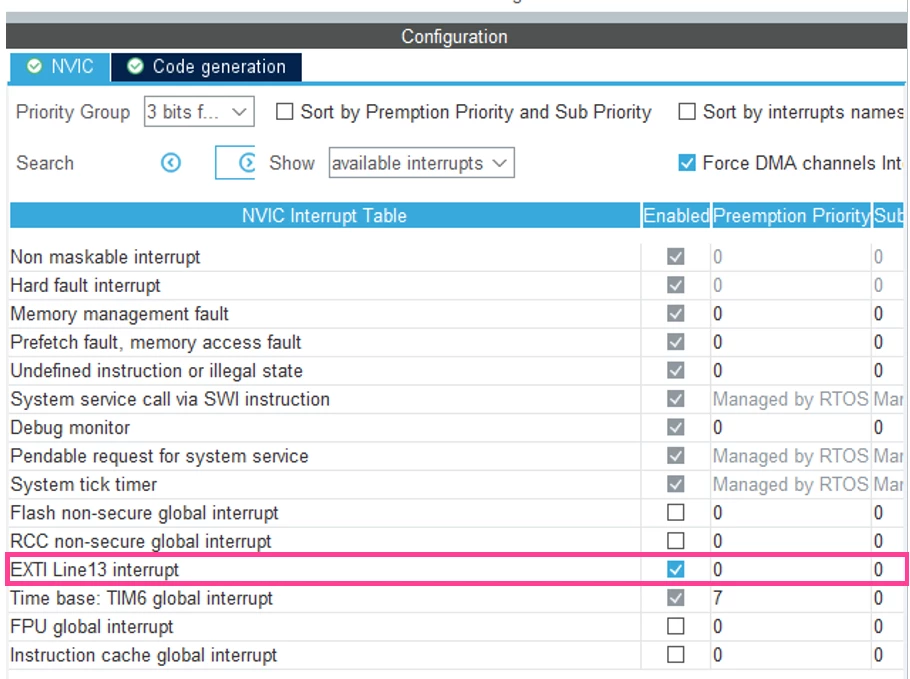 Figure 15: Overview of NVIC settings shown under “System Core” tab -> “NVIC”.
2.8 Other project configurations
In figure 16 below, we modify the visibility of the GPIO initialization function because we use it inside the source file for our RTOS application.
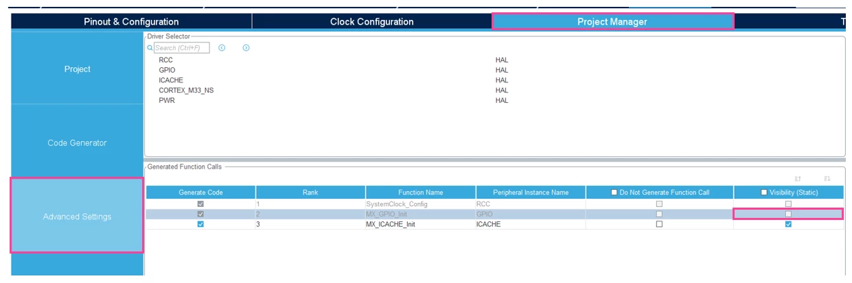 Figure 16: Uncheck visibility (static) so this function is not declared as static to allow for global function visibility.
Finally, we are ready to generate our source files from the STM32CubeMX .ioc file we configured. Before doing that, we set all unused pins to analog to save power consumption.
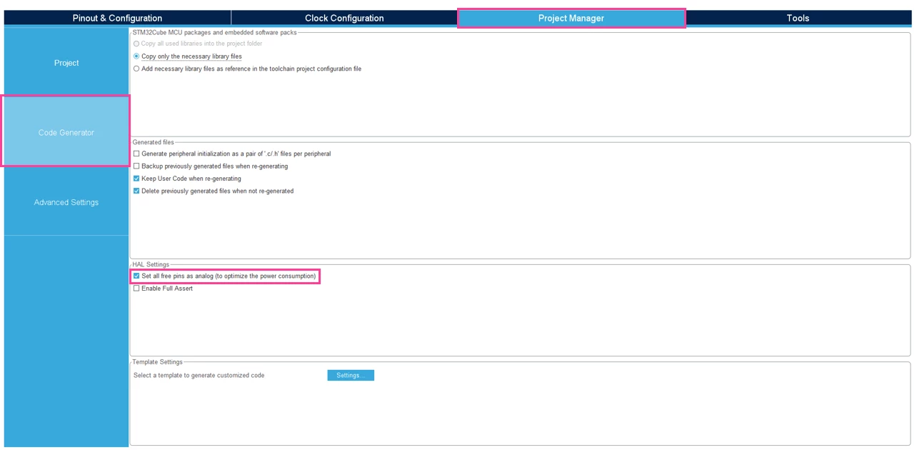 Figure 17: Configure unused pins as analog to save more power.
As a final step, save your project and then generate your code as shown. You can define your project location/workspace anywhere you like but make sure that the project path is not too long or else you will encounter issues with the IDE. Under “Toolchain/IDE,” select STM32CubeIDE.
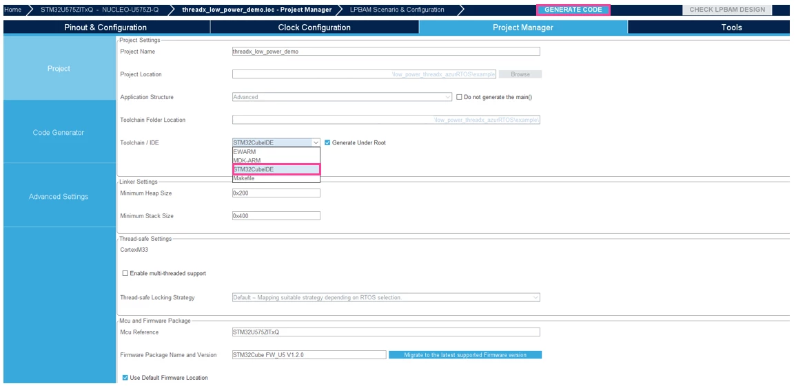 Figure 18: Choose “STM32CubeIDE” for Toolchain/ IDE & then click “GENERATE CODE”.
3 Coding your application using STM32CubeIDE
This topic continues in part 2, click here to view
Links
- https://www.st.com/resource/en/schematic_pack/mb1549-u575ziq-c03_schematic.pdf
- https://www.st.com/resource/en/reference_manual/rm0456-stm32u5-series-armbased-32bit-mcus-stmicroelectronics.pdf
- https://www.st.com/content/dam/AME/2023/MDG/low-power-threadx-example-v1.zip
- https://learn.microsoft.com/en-us/azure/rtos/threadx/chapter1
- https://www.st.com/en/development-tools/stm32cubemx.html
- https://www.st.com/en/development-tools/stm32cubeide.html
- https://www.st.com/en/development-tools/stm32cubemonpwr.html
