


How to use boot selection in STM32C5
Summary
This article explains the STM32C5 boot modes and how they are selected using the BOOT0 pin, BOOT_SEL and BOOT0 option bits, BOOTADD, BOOT_LOCK, and the EMPTY flag. It is based on the STM32C55x/C56x reference manual.
Introduction
The STM32C5 microcontroller series offers a flexible boot architecture that lets developers choose, secure, and update the firmware boot source with fine control. This flexibility is key to supporting reliable in-field firmware updates, secure production programming, and safe recovery during development and large-scale deployment. To design a robust system, it is important to understand how the device selects its boot source at reset. This article is based on the STM32C55x/C56x reference manual (RM0522), the STM32C56x datasheet, and application note AN2606.
1. Boot sources and the BOOTADD option
STM32C5 devices can boot from two primary memory areas: User flash and system memory. User flash contains the main user application, while system memory hosts a factory-programmed embedded bootloader used for maintenance and programming.
When the device is configured to boot from user flash, the specific start address is defined by the BOOTADD option byte (bits 31:8). This option field points to a word-aligned address within the main flash memory. At reset, the core fetches the initial stack pointer and reset vector from this location. This mechanism offers significant architectural freedom, allowing developers to relocate the application start address to implement complex schemes. This applies to scenarios such as dual-bank firmware updates or maintaining a small user bootloader at a low address while the main application resides at a higher address.
2. Boot selection logic
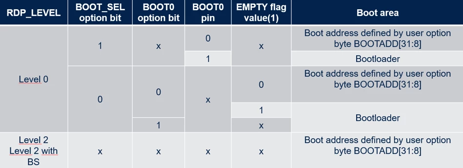
The decision of which area to boot from is driven by a combination of the BOOT0 pin, the BOOT_SEL option bit, and the readout protection (RDP) level.
In a standard configuration with RDP level 0 (no readout protection), the interaction between hardware and software defines the boot source. If the BOOT_SEL option bit is cleared (0), the BOOT0 pin is active and dictates the boot mode. A high or low state on the pin directs the system to system memory or user flash, respectively.
Conversely, if BOOT_SEL is set (1), the physical BOOT0 pin is ignored. In this state, the device is forced to boot from the address defined by BOOTADD in user flash, ensuring a deterministic startup regardless of external pin states. However, this forced boot can still be overridden by the empty check mechanism.
3. EMPTY check mechanism
To prevent the system from attempting to execute code from an unprogrammed memory location, the STM32C5 implements an automatic empty check. During the option byte loading phase at reset, the flash memory interface reads the 32-bit word located at the address defined by BOOTADD.
If this word equals 0xFFFF FFFF, the location is considered empty. This status is reflected in the EMPTY bit of the flash access control register (FLASH_ACR). If the user flash is determined to be empty (EMPTY = 1), the system overrides the standard boot selection and automatically falls back to the embedded bootloader in system memory. This feature ensures that fresh or mass-erased devices have a recovery path, allowing programming via the supported interfaces without manual pin intervention. The EMPTY status can be read and modified by software, allowing applications to force a bootloader entry on the next reset by manipulating the FLASH_ACR register.
4. Securing the boot configuration
In production devices, security is often a top priority. The BOOT_LOCK option bit can be used to freeze the boot configuration. When BOOT_LOCK is set, changes to boot-related option bytes are blocked, this includes the BOOTADD, BOOT_SEL, and the BOOT0 option bit. This helps protect the device from accidental or malicious changes to the boot address during in-field firmware updates, ensuring that the application always starts from the intended trusted address.
It is important to highlight that the BOOT_LOCK protection does not disable the empty check mechanism. Even if the boot configuration is locked, the system still verifies if the flash is programmed. If the application becomes corrupted or erased (appearing as empty), the device can still safely fall back to the embedded bootloader for recovery.
5. Embedded bootloader
The embedded bootloader is a permanent piece of firmware located in the read-only system memory region, programmed by STMicroelectronics during production. The native bootloader supports a wide variety of communication interfaces, including USART, SPI, FDCAN, and USB in device firmware upgrade (DFU) mode, all depending on the specific device and package. A detailed protocol, pinout, feature, and entry conditions for these interfaces are available in the application note AN2606.
5.1 Prerequisites
- Board powered and connected to a PC via ST‑LINK.
- STM32CubeProgrammer installed and launched.
5.2 Connect to the target
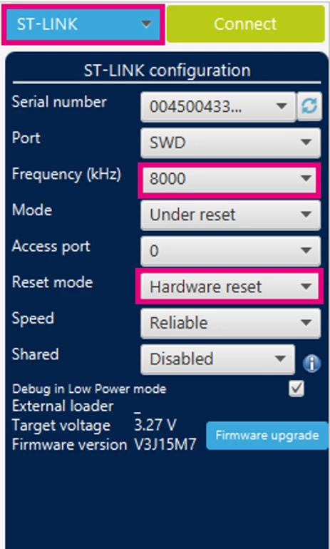
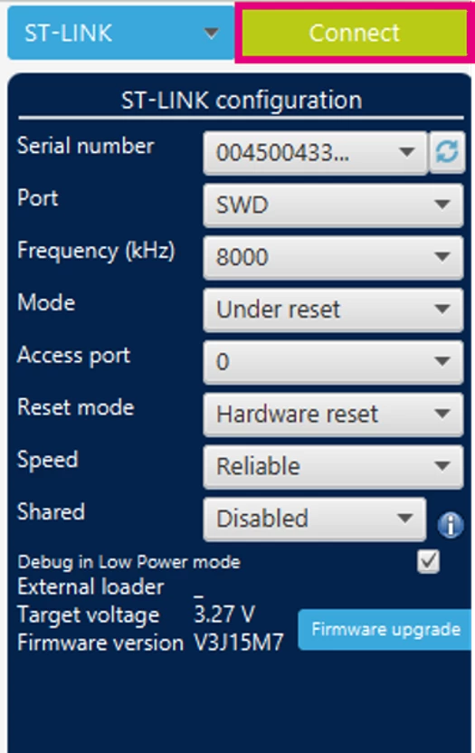
- In the top‑right ST‑LINK panel:
- Select ST‑LINK as the connection mode.
- Keep the default SWD frequency and reset mode (for example, hardware reset).
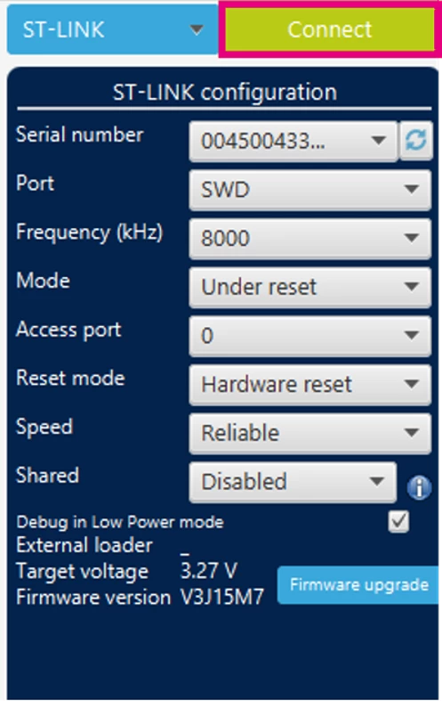
- Click [Connect].
5.3 Open the option bytes view
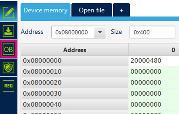
- In the left toolbar, click the “OB” (option bytes) icon.
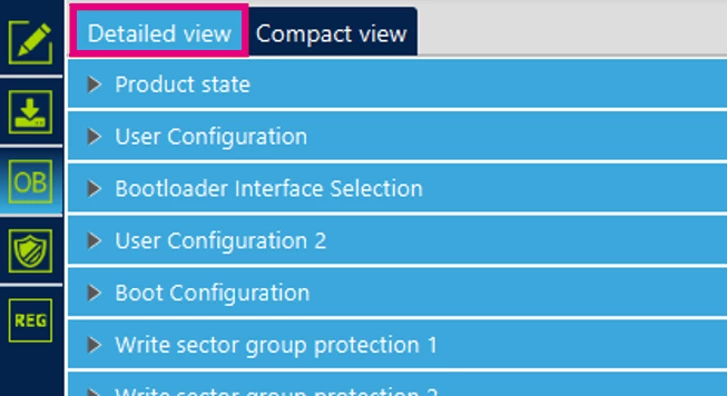
- Ensure “Detailed view” is selected (top left of the option‑bytes pane).
5.4 Configure boot to system memory (system bootloader)
This uses the BOOT_SEL and BOOT0 option bits.
- In the User Configuration section:
- Ensure BOOT_SEL is unchecked
→ This makes the device take the BOOT0 value from the option bit rather than only from the pin (see RM0522 / AN2606).
- Ensure BOOT_SEL is unchecked

-
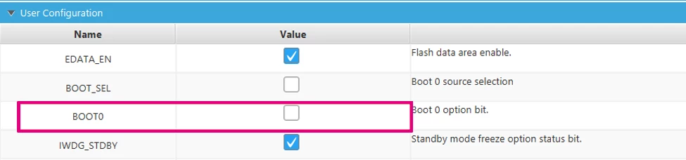
- Select the BOOT0 checkbox
→ For STM32C5, a BOOT0 value of 1 (checked) selects the system memory bootloader instead of user flash (refer to the boot mode table in RM0522).
- Select the BOOT0 checkbox

- (Optional but recommended) in the “Bootloader Interface Selection”:
- Leave BLI_COM_CFG = 0xFFFFFFFF if all bootloader interfaces should be enabled (USART/SPI/FDCAN/USB DFU as per AN2606).
- Or set BLI to enable only the interface planned for use.

- Verify in “Boot Configuration” that:
- BOOTADD remains at the normal user flash start (Value 0x80000, Address 0x08000000).
(This does not affect system‑memory boot, but keep in mind that it might be needed to assert it when returning to user‑flash boot).
- BOOTADD remains at the normal user flash start (Value 0x80000, Address 0x08000000).

- If BOOT_LOCK is set to a value that prevents changes, it is not possible to modify these bits.
- In that case, follow RM0522/AN2606 procedures (usually involves a mass erase or RDP change) before repeating this step.

5.5 Program the new option bytes
- At the bottom of the option‑byte pane, click [Apply].
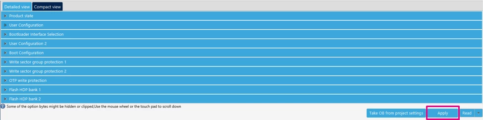
- Confirm the option byte programming dialog.
- CubeProgrammer will erase/program one or more affected OB words and automatically reset the device.
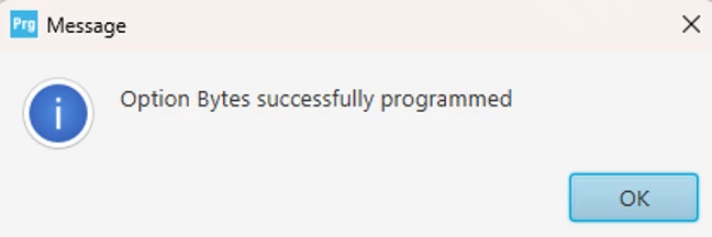
After the reset, the STM32C5 does not jump to user flash but starts from the system memory and runs the native system bootloader.
5.6 Use the system bootloader
The device is in system boot:
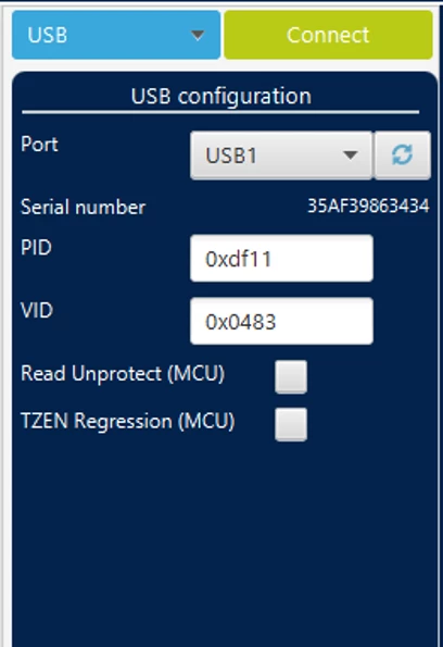
- Connect via the desired interface, in this case, USB is used:
- For DFU over USB: run a DFU tool (for example, CubeProgrammer in USB mode) and connect.
-
- For USART/SPI/FDCAN: use the corresponding host interface from CubeProgrammer or your own tool. It may be necessary to change the port and find the one that matches your Nucleo board.
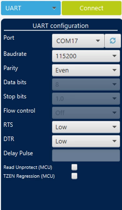
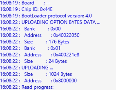
- Perform the flash programming/erase/firmware update through the bootloader.
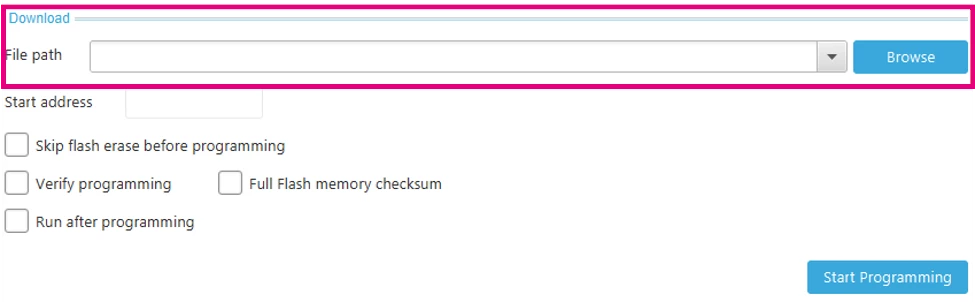
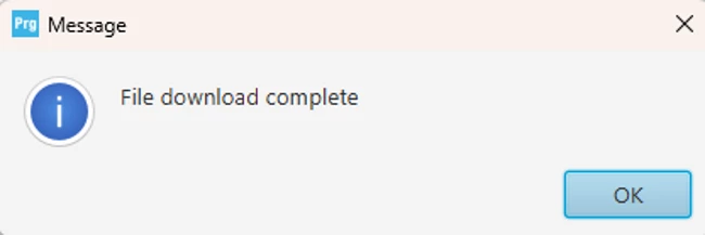
5.7 Restore normal boot to user flash
If the BOOT0 option is not changed back, the MCU always returns to system boot.
- Reconnect via ST‑LINK in CubeProgrammer.
- Open “Option bytes” → “User Configuration”.
- Keep BOOT_SEL unchecked and set BOOT0 back to unchecked (0).
- This restores the boot from user flash at BOOTADD.
- Click Apply, confirm, and let the device reset.
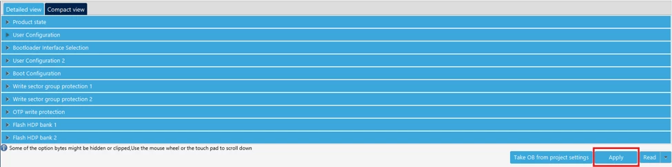
The STM32C5 boots your application from main flash on every reset.
Conclusion
The STM32C5 boot architecture provides a robust, secure, and flexible foundation for embedded applications. By effectively coordinating BOOT0, BOOT_SEL, and BOOTADD, and leveraging the safety net provided by the EMPTY flag, developers can ensure that their systems perform reliably from the first programming on the assembly line to secure firmware updates in the field.
Related links
- Application note AN2606: Introduction to system memory boot mode on STM32 MCUs
- STM32 embedded software documentation
- STM32CubeMX2 documentation
- STM32CubeProgrammer
- Reference manual RM0522: STM32C5 Arm®-based 32-bit MCUs
- Datasheet DS14927: TM32C562xx