

How to set up and run the I3C_Private_Command_IT controller and target example projects
- 0 replies
- 1748 views
Summary
This article is a tutorial on how to set up and run the I3C_Controller_Private_Command_IT and I3C_Target_Private_Command_IT example projects. This tutorial uses the NUCLEO-H563ZI board and can be followed with any other ST development board that has an I3C_Private_Command_IT type example project available for it.
Refer to each example project’s README.md file for detailed descriptions of how the example works. Furthermore, the I3C_Controller_Private_Command_IT and I3C_Target_Private_Command_IT example projects can be tailored to any STM32 MCU or development board that has an I3C peripheral, such as the STM32H503, STM32H7R & STM32H7S MCUs.
Prerequisites
- Two NUCLEO-H563ZI boards. Can be purchased in our eStore here.
- Three male-to-male jumper wires
- Two USB Type-C® to USB-A cables
- STM32CubeIDE installed
1. Board connections
Connect the NUCLEO-H563ZI controller (left) and NUCLEO-H563ZI target (right) boards together using the following connections.
Controller PB8 (SCL) -> Target PB8 (SCL)
Controller PB9 (SDA) -> Target PB9 (SDA)
Controller GND -> Target GND
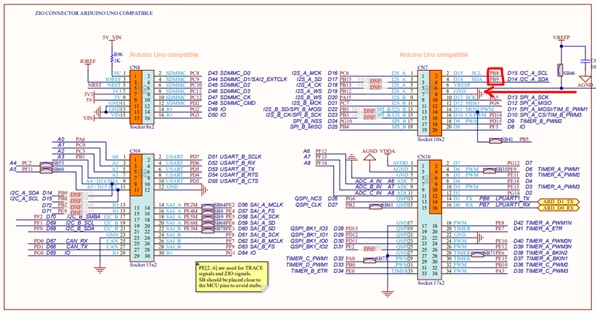 Fig 1. NUCLEO-H563ZI board schematic
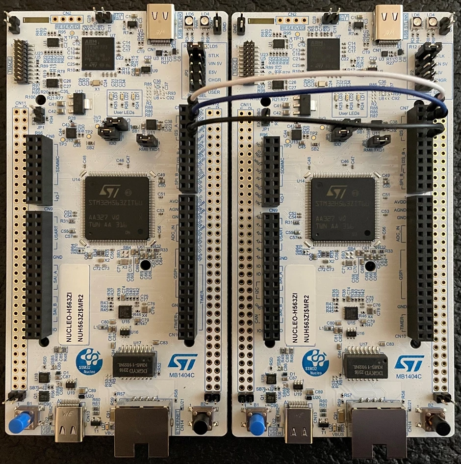 Fig 2. Controller (left) & target (right) board connections
2. Import example projects into STM32CubeIDE
Create a new project in STM32CubeIDE, then use the "Example Selector" tab to search for and select the I3C_Controller_Private_Command_IT example project for the NUCLEO-H563ZI board.
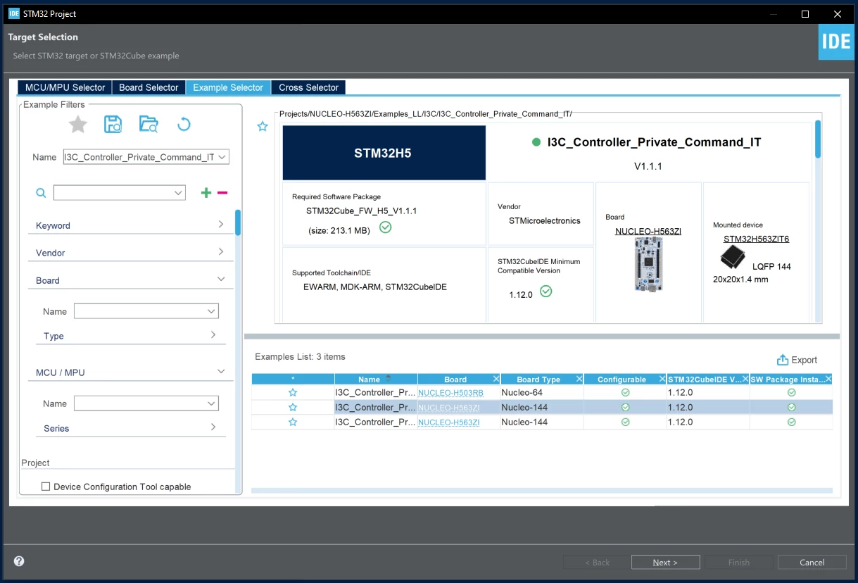 Fig 3. CubeMX - I3C_Controller_Private_Command_IT example project
Once the project is imported, click the build icon to compile the project.
Create another new project in the same STM32CubeIDE workspace and use the "Example Selector" tab to search for and select the I3C_Target_Private_Command_IT example project for the NUCLEO-H563ZI board.
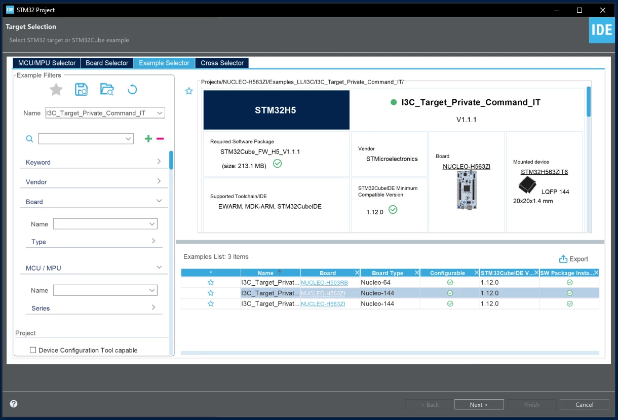 Fig 4. CubeMX - I3C_Target_Private_Command_IT example project
Once the project is imported, click the build icon to compile the project.
3. Flash boards with example projects
First, plug the NUCLEO-H563ZI controller board into your computer. In the "Debug Configurations" window for the controller example project, check the "ST-LINK S/N" box, click "Scan", and select this board’s "ST-LINK S/N."
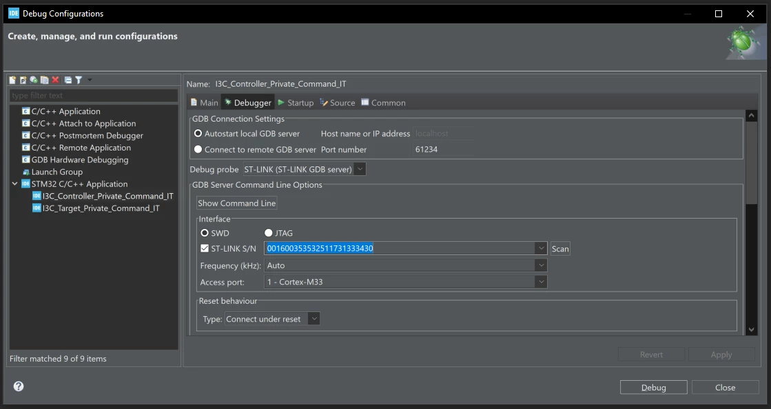 Fig 5. CubeIDE debug configurations - controller project
Then click "Debug" to flash the project to the controller board. Once the board is flashed, terminate the debug session. Make sure that the code is running on the controller board (LD1 should be flashing roughly three blinks per second).
Keeping the controller board plugged in, now plug the NUCLEO-H563ZI target board into your computer. In the "Debug Configurations" window for the target example project, check the "ST-LINK S/N" box, click "Scan", and select this board’s ST-LINK S/N.
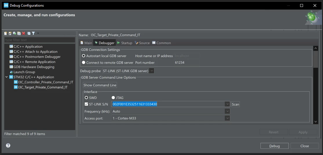 Fig 6. CubeIDE debug configurations - target project
Then click Debug to flash the project to the target board. Once the board is flashed, terminate the debug session.
4. Test the controller board example project
Launch a debug session for the controller example project and place breakpoints at lines 213, 216 & 221 for testing purposes. Add the buffers aTxBuffer and aRxBuffer to the expressions tab so we can monitor their values.
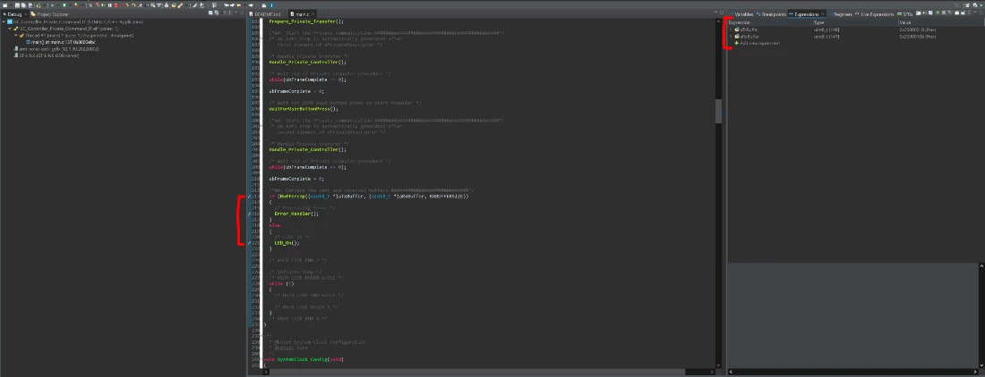 Fig 7. CubeIDE breakpoints & watched expressions - controller project
Now, click the "Run/Resume" icon to run the code on the controller board. LD1 on the controller board should be blink fast (roughly three blinks per second). LD1 on the target board should be off.
|
Board |
LD1 status |
|
Controller |
Fast blinking |
|
Target |
Off |
On the controller board, press the blue user button once. LD1 on the controller board should still be fast blinking (roughly three blinks per second). LD1 on the target board should now be solid green.
|
Board |
LD1 status |
|
Controller |
Fast blinking |
|
Target |
On |
On the controller board, press the blue user button once. LD1 on the controller board should still be fast blinking (roughly three blinks per second). LD1 on the target board should now be off.
|
Board |
LD1 status |
|
Controller |
Fast blinking |
|
Target |
Off |
On the controller board, press the blue user button once. LD1 on the controller board should now be solid green. LD1 on the target board should also be solid green. In the debugger, the breakpoint at line 213 should be hit.
|
Board |
LD1 status |
|
Controller |
On |
|
Target |
On |
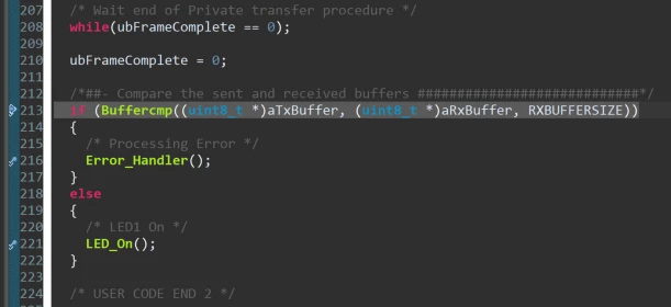 Fig 8. CubeIDE line 213 breakpoint - controller project
Click the Run/Resume icon and the breakpoint at line 221 should be hit. At this point, check the details field of the aRxBuffer. It should contain the same " ****I3C_TwoBoards communication based on IT**** …" message that is in the aTxBuffer.
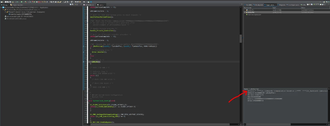 Fig 9. CubeIDE line 221 breakpoint - controller project
Note: If the breakpoint at line 216 (Error_Handler()) is hit or if either of the boards have a slow blink on LD1 (roughly one blink per second), then an I3C transmission or reception error has occurred.
You have finished testing the example on the controller board. Before continuing, terminate the debug session and then press the black reset button on the target board (right) first, then press the black reset button on the controller board (left).
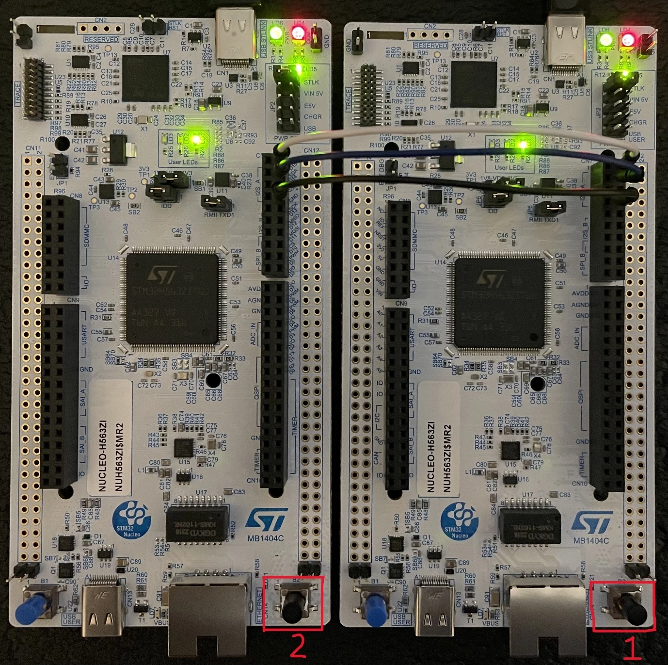 Fig 10. Example finished - controller (left) & target (right) boards
LD1 on the controller board should be fast blinking (roughly three blinks per second). LD1 on the target board should be off.
|
Board |
LD1 status |
|
Controller |
Fast blinking |
|
Target |
Off |
5. Test the target board example project
Launch a debug session for the target example project and place breakpoints at lines 129, 132 & 137 for testing purposes. Add the buffers aTxBuffer and aRxBuffer to the expressions tab so we can monitor their values.
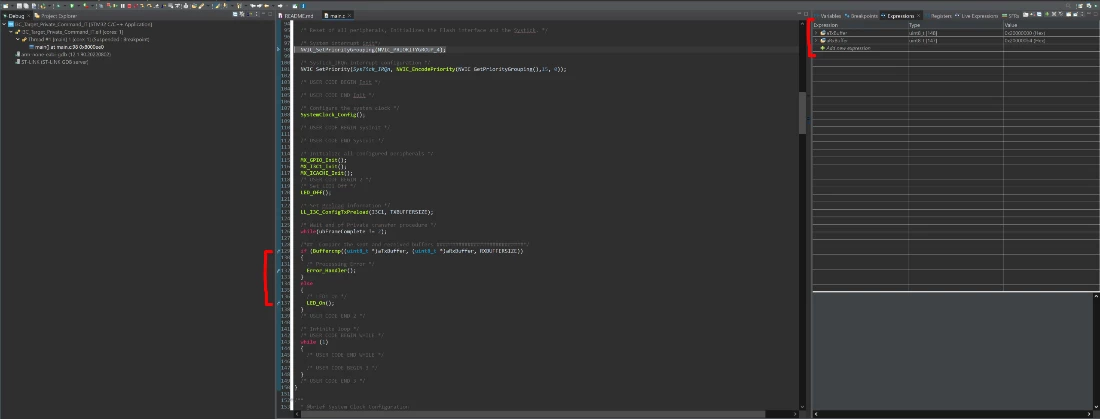 Fig 11. CubeIDE breakpoints & watched expressions - target project
Now, click the "Run/Resume" icon to run the code on the target board. LD1 on the controller board should be fast blinking (roughly three blinks per second). LD1 on the target board should be off.
|
Board |
LD1 status |
|
Controller |
Fast blinking |
|
Target |
Off |
On the controller board, press the blue user button once. LD1 on the controller board should still be fast blinking (roughly three blinks per second). LD1 on the target board should now be solid green.
|
Board |
LD1 status |
|
Controller |
Fast blinking |
|
Target |
On |
On the controller board, press the blue user button once. LD1 on the controller board should still be fast blinking (roughly three blinks per second). LD1 on the target board should now be off.
|
Board |
LD1 status |
|
Controller |
Fast blinking |
|
Target |
Off |
On the controller board, press the blue user button once. LD1 on the controller board should now be solid green. LD1 on the target board should also be solid green. In the debugger, the breakpoint at line 129 should be hit.
|
Board |
LD1 status |
|
Controller |
On |
|
Target |
On |
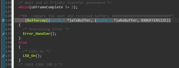 Fig 12. CubeIDE line 129 breakpoint - target project
Click the Run/Resume icon and the breakpoint at line 137 should be hit. At this point, check the details field of the aRxBuffer. It should contain the same " ****I3C_TwoBoards communication based on IT**** …" message that is in the aTxBuffer.
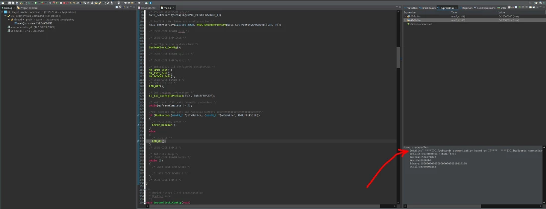 Fig 13. CubeIDE line 137 breakpoint - target project
Note: If the breakpoint at line 132 (Error_Handler()) is hit or if either of the boards have a slow blink on LD1 (roughly one blink per second), then an I3C transmission or reception error has occurred.
You have finished testing the example on the target board. Terminate the debug session and then press the black reset button on the target board (right) first, then press the black reset button on the controller board (left).
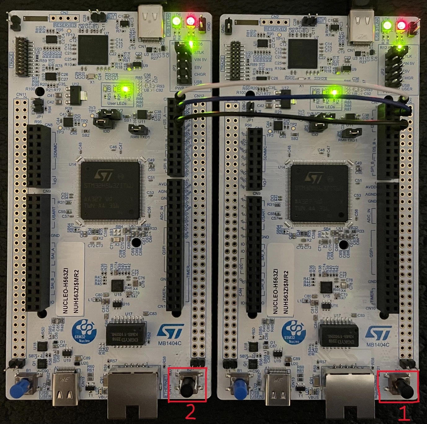 Fig 14. Example finished - controller (left) & target (right) boards
LD1 on the controller board should be fast blinking (roughly three blinks per second). LD1 on the target board should be off.
|
Board |
LD1 status |
|
Controller |
Fast blinking |
|
Target |
Off |
The boards are now ready to run through the example again.
