

How to measure and reduce current consumption on STM32U3xx devices using power examples
Introduction and use case
This article explains how to measure the MCU current of the STM32U3xx devices and how to interpret the STM32U3 power example results. It focuses on the STM32U3 power examples, the MCU IDD measurement path, and the firmware choices that influence low-power current.
The current values shown in this article are documented reference values from the STM32U3 power example documentation. They are useful for comparison, but your own measurements depend on the board setup, jumper configuration, debug state, supply conditions, firmware build, and measurement instrument. An external current measurement instrument, including STM32-LPM01-XN, can be used when it is inserted in series in the correct MCU IDD path according to the board and tool documentation.
The STM32U3 devices support several operating modes that let an application trade performance, wake-up behavior, retained state, and current consumption. A typical low-power optimization flow is:
-
Measure a run mode baseline.
-
Select the lowest power mode that still supports the required wake-up source and retained state.
-
Remove unnecessary clocks, peripherals, debug retention, SRAM retention, and RTC features.
-
Remeasure the steady low-power plateau in a repeatable hardware state.
The STM32U3 power examples are useful because they isolate many of these choices. The standalone examples show individual modes such as Sleep, Stop, Standby, and Shutdown. PWR_ModesSelection is especially useful for relative comparisons because several scenarios are selected and measured within one application.
List of Figures
-
Figure 1. Board Setup
List of Tables
-
Table 1. Measurement conditions to record
-
Table 2. Standalone power example reference currents for NUCLEO-U385RG-Q
-
Table 3. PWR_ModesSelection reference currents for NUCLEO-U385RG-Q
-
Table 4. PWR_ModesSelection current comparison across NUCLEO-U3 boards
1. Hardware and software prerequisites
Use the following items:
- NUCLEO-U385RG-Q board with the STM32U385RGTxQ device
- STM32U3 firmware package containing the power examples.
- One of the following current measurement instruments:
- A suitable ammeter
- A power analyzer
- STM32-LPM01-XN, inserted in the correct IDD current path according to the board and tool documentation.
- A serial terminal for PWR_ModesSelection
- A tool chain supported by the selected example.
Relevant STM32U3 power examples include:
- PWR_RUN_SMPS
- PWR_SLEEP
- PWR_STOP0
- PWR_STOP1
- PWR_STOP2
- PWR_STOP3
- PWR_STANDBY
- PWR_SHUTDOWN
- PWR_ModesSelection
Use PWR_RUN_SMPS as the recommended run mode baseline before comparing lower-power modes.
2. Measurement setup
Measure the MCU current in the MCU IDD path. The example documentation describes current measurement using the board IDD path, typically by removing JP4 and inserting the measurement instrument in series. If a specific RTC Stop 3 example or board note specifies a JP5 path instead, follow that example documentation. Using the wrong jumper or measurement path can include or exclude board circuitry and produce misleading current values.
For an external instrument such as STM32-LPM01-XN, do not assume that connecting the tool anywhere on the board gives the MCU current. Insert the instrument in series in the documented MCU IDD path, using the board and tool documentation.
Several low-power examples are not intended to be measured while an active debug session is running. Disabling debug Stop or Standby bits in firmware helps reduce debug-related current, but it is not enough if the debugger remains actively connected and controlling execution.
Also check board-level leakage conditions. Very low current measurements can be affected by the ST-LINK power state and by leakage on PA13 when the MCU is externally supplied while the ST-LINK side is not supplied. If the example documentation recommends configuring PA13 as analog to reduce leakage, note that this can affect debugger connectivity. Keep the board in a documented and repeatable hardware state for every measurement.
3. Measurement conditions to record
Record the following conditions with every current value.
Table 1. Measurement conditions to record
| Item | Recommended entry |
| Board | NUCLEO-U385RG-Q |
| MCU | STM32U385RGTxQ device |
| Supply voltage | 3.3 V for the reference values shown in this article |
| Regulator mode | SMPS enabled for the reference values shown in this article |
| Firmware context | Exact example and selected scenario |
| Measurement point | MCU IDD path, with the jumper configuration specified by the example documentation |
| Measurement instrument | Ammeter, power analyzer, or STM32-LPM01-XN connected in series in the IDD path |
| Debug state | No active debug session for final low-power data |
| Wake-up source | User button, RTC, or other source used by the selected example |
| RTC state | Enabled or disabled |
| SRAM retention | Full retention, 8 Kbyte retention, or no retention |
| Acquisition window | Steady low-power plateau, separated from entry and wake-up transients |
| Additional comparison data | Board revision, firmware package revision, toolchain/build, temperature, and acquisition method |
4. Reference current values and how to interpret them
The following values are documented reference values from the STM32U3 power example documentation for NUCLEO-U385RG-Q, SMPS enabled, and 3.3 V. They are not presented as direct STM32-LPM01-XN measurements.
Use them to understand the expected range and trend. For strict comparison, reproduce the same hardware state, firmware configuration, and measurement path.
-
Standalone example reference values
Table 2. Standalone power example reference currents for NUCLEO-U385RG-Q
| Example | Mode documented by the example | Reference current |
| PWR_RUN_SMPS | Run with SMPS | 1369 uA |
| PWR_SLEEP | Sleep (SMPS with 96MHz) | 768 uA |
| PWR_STOP0 | Stop 0(Range1 -96MHz) | 209.4 uA |
| PWR_STOP1 | Stop 1 | 53.26 uA |
| PWR_STOP2 | Stop 2 | 4.43 uA |
| PWR_STOP3 | Stop 3 | 2.33 uA |
| PWR_STANDBY | Standby | 0.545 uA |
| PWR_SHUTDOWN | Shutdown | 0.523 uA |
These examples are useful for understanding the broad current progression from Run to Sleep, Stop, Standby, and Shutdown. Do not blindly compare a standalone example with a PWR_ModesSelection scenario unless the firmware configuration and retained resources are equivalent.
-
PWR_ModesSelection reference values
PWR_ModesSelection is useful for relative comparisons within one application because it applies several selectable scenarios in a common firmware context.
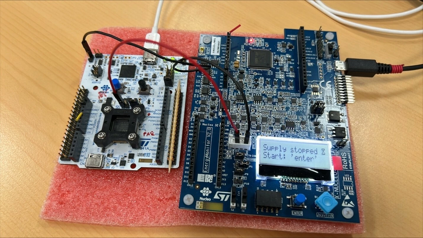
Table 3. PWR_ModesSelection reference currents for NUCLEO-U385RG-Q
| PWR_ModesSelection scenario | Reference current |
| Run, 96 MHz | 1213 uA |
| Run, 48 MHz | 460.8 uA |
| Sleep, 12 MHz | 111.6 uA |
| Stop 1, full SRAM retention | 50.53 uA |
| Stop 1, 8 Kbyte SRAM retention5 | 43.81 uA |
| Stop 2, full SRAM retention | 4.381 uA |
| Stop 2, 8 Kbyte SRAM retention | 3.737 uA |
| Stop 3, full SRAM retention | 2.108 uA |
| Stop 3, 8 Kbyte SRAM retention | 1.524 uA |
| Standby, 8 Kbyte SRAM retention, RTC, ULPMEN=1 | 1.03 uA |
| Standby, no SRAM retention, RTC, ULPMEN=1 | 0.916 uA |
| Standby, no SRAM retention, no RTC, ULPMEN=1 | 0.395 uA |
| Shutdown with RTC | 0.801 uA |
| Shutdown without RTC | 0.343 uA |
The following comparison uses the documented PWR_ModesSelection README values from the available STM32U3 NUCLEO board examples. Values are in uA. The U345, U366, and U385 README files use the JP4 IDD measurement path; the U3A6 and U3C5 README files use the JP5 IDD measurement path.
Table 4. PWR_ModesSelection current comparison across NUCLEO-U3 boards
| PWR_ModesSelection scenario | NUCLEO-U345RC-Q | NUCLEO-U366RET6-Q | NUCLEO-U385RG-Q | NUCLEO-U3C5ZI-Q |
| Run, 96 MHz | 2085 | 2057 | 1213 | 1461 |
| Run, 48 MHz | 773.8 | 781.8 | 460.8 | 538.2 |
| Sleep, 12 MHz | 105.8 | 108.8 | 111.6 | 145.3 |
| Stop 1, full SRAM retention | 54.3 | 59.3 | 50.53 | 65.89 |
| Stop 1, 8 Kbyte SRAM retention | 51.46 | 56.46 | 43.81 | 46.41 |
| Stop 2, full SRAM retention | 5.90 | 6.30 | 4.381 | 3.33 |
| Stop 2, 8 Kbyte SRAM retention | 5.44 | 5.34 | 3.737 | 3.08 |
| Stop 3, full SRAM retention | 2.058 | 1.498 | 2.108 | 1.52 |
| Stop 3, 8 Kbyte SRAM retention | 1.914 | 1.34 | 1.524 | 1.37 |
| Standby, 8 Kbyte SRAM retention, RTC, ULPMEN=1 | 1.041 | 1.32 | 1.03 | 1.09 |
| Standby, no SRAM retention, RTC, ULPMEN=1 | 0.88 | 1.15 | 0.916 | 0.85 |
| Standby, no SRAM retention, no RTC, ULPMEN=1 | 0.446 | 0.64 | 0.395 | 0.42 |
| Shutdown with RTC | 0.823 | 1.1 | 0.801 | 0.82 |
| Shutdown without RTC | 0.38 | 0.634 | 0.343 | 0.35 |
The tables show three important trends:
-
Reducing Run frequency can significantly reduce Run current.
-
Reducing SRAM retention lowers Stop and Standby current.
-
Disabling RTC lowers deep low-power current when RTC timekeeping or RTC wakes up is not required.
5. Step-by-step procedure
-
Choose an example.
Start with PWR_RUN_SMPS to establish the Run-mode baseline. Then choose a lower-power example such as PWR_SLEEP, PWR_STOP2, PWR_STOP3, PWR_STANDBY, or PWR_SHUTDOWN.
Use PWR_ModesSelection when you want to compare several scenarios within one application.
-
Build and program the example.
Build the selected example with a supported tool chain and program the board. After programming, stop the active debug session before taking final low-power measurements.
-
Prepare the board current measurement path.
Configure the board for MCU IDD measurement according to the example documentation. For most examples, this means removing JP4 and inserting the current measurement instrument in series in the MCU IDD path. If an RTC Stop 3 example or board note specifies JP5, follow that specific instruction.
-
Connect the measurement instrument.
Use an ammeter, power analyzer, or STM32-LPM01-XN in series in the IDD path. Do not measure from a point that includes unintended board loads unless that is the current you want to characterize.
-
Remove active debug influence.
For final low-power current data, run without an active debug session. Program the board, detach the debugger, then reset or power-cycle the board as required. This is important for Stop, Standby, and Shutdown measurements.
-
Trigger the low-power state.
For user-button examples, follow the example behavior described in the documentation. User-button wake-up examples commonly use wake-up line 2.
RTC-based scenarios use RTC wake-up where applicable. Do not describe all scenarios as using one wake-up line; check the selected example.
-
Use the serial menu for PWR_ModesSelection.
Open a serial terminal with the configuration used by the example:
- 115200 baud
- 8 data bits
- No parity
- 1 stop bit
- No flow control
Select the scenario to measure. The application uses the serial interface for selection, then prepares the low-power state.
For PWR_ModesSelection, keep the ST-LINK/VCP connection in the documented powered state for menu selection, but do not keep an active debug session attached during final measurement.
- Capture the correct current window.
Record the steady-state low-power plateau. Do not average setup code, serial menu activity, low-power entry transients, wake-up transients, or reset current unless the goal is full application energy over time.
-
Compare in the correct context.
Compare the measurement with the documented reference value for the same example and scenario. Compare deltas within PWR_ModesSelection when analyzing frequency, RTC, or SRAM retention impact. Avoid drawing conclusions from values measured in different applications unless the configurations are known to match.
6. Practical optimization guidance
-
Start from a Run baseline
Use PWR_RUN_SMPS as the baseline because the documented reference values use SMPS enabled at 3.3 V. This makes later comparisons easier to interpret.
-
Reduce frequency when performance allows
PWR_ModesSelection reports 1890 uA at 96 MHz and 775.8 uA at 48 MHz. A lower clock can reduce instantaneous current but always measure the full workload if execution-time changes.
-
Suspend periodic wake-up sources
Sleep and Stop measurements can be disturbed by periodic interrupts. The examples suspend the HAL tick before entering low power, so the SysTick interrupt does not wake the MCU immediately.
Example Sleep pattern:
HAL_SuspendTick();
HAL_PWR_EnterSLEEPMode(PWR_MAINREGULATOR_ON, PWR_SLEEPENTRY_WFI);
Example Stop pattern:
HAL_SuspendTick();
HAL_PWR_EnterSTOPMode(PWR_LOWPOWERMODE_STOP2, PWR_STOPENTRY_WFI);
Use the low-power mode and entry instruction that match the selected example.
-
Deinitialize setup peripherals
Peripherals used only for setup or user interaction can add current if left active. PWR_ModesSelection uses USART1 for menu selection and then de-initializes it before entering the selected low-power scenario.
USART1_UART_DeInit();
lowpower_config_scenario();
-
Run without active debug for final data
PWR_ModesSelection disables debug support in Stop and Standby:
HAL_DBGMCU_DisableDBGStopMode();
HAL_DBGMCU_DisableDBGStandbyMode();
These calls clear the debug Stop and Standby behavior in DBGMCU_CR, but they do not replace the need to detach the active debug session for final measurement.
-
Retain only the SRAM that is needed
SRAM retention preserves state but costs current. PWR_ModesSelection shows lower Stop current with 8 Kbyte retention than with full SRAM retention.
Example pattern for reducing Stop retention:
HAL_PWREx_DisableRAMsContentStopRetention(PWR_SRAM1_FULL_STOP_RETENTION);
HAL_PWREx_DisableRAMsContentStopRetention(PWR_SRAM2_FULL_STOP_RETENTION);
HAL_PWREx_EnableRAMsContentStopRetention(PWR_SRAM2_PAGE3_STOP_RETENTION);
Use this approach only when the application state required after wake-up is placed in retained memory.
-
Understand RTC and LSE impact
RTC operation requires a clock source, typically LSE. The RTC-enabled scenarios in PWR_ModesSelection configure LSE low drive:
__HAL_RCC_LSEDRIVE_CONFIG(RCC_LSEDRIVE_LOW);
On STM32U385, this configures RCC_BDCR.LSEDRV[1:0] to the low-drive setting. Lower LSE drive helps reduce current, but the drive must still be sufficient for reliable crystal startup and oscillation across the product conditions.
-
Use ULPMEN correctly in Standby
The Standby scenarios in PWR_ModesSelection include ULPMEN=1. The Standby examples enable ultra-low-power mode before entering Standby:
HAL_PWREx_EnableUltraLowPowerMode();
ULPMEN is PWR_CR1 bit 7. In RM0556, it controls BOR0 ultra-low-power behavior in Standby and is relevant only when BOR level 0 is selected. Standby keeps BOR active and enabling ULPMEN allows BOR0 to operate in discontinuous ultra-low-power behavior, which helps reach the lowest Standby current.
This means that the Standby rows are complete scenarios, not just “enter Standby mode,” RTC state, SRAM2 retention, ULPMEN, and BOR configuration all matter.
-
Disable unused supply-valid paths and Stop kernel clocks
PWR_ModesSelection also removes unused supply-valid paths, battery charging, SRAM fast wake-up, and forced Stop kernel clocks when they are not needed:
HAL_PWREx_DisableSRAM2ContentStandbyRetention(PWR_SRAM2_FULL_STANDBY_RETENTION);
HAL_PWREx_DisableSRAMFastWakeUp();
HAL_PWREx_DisableVddA();
HAL_PWREx_DisableVddIO2();
HAL_PWREx_DisableVddUSB();
HAL_PWREx_DisableBatteryCharging();
HAL_RCCEx_DisableKernelClkInStop(RCC_KERNELCLK_MSIK);
HAL_RCCEx_DisableKernelClkInStop(RCC_KERNELCLK_HSI);
These calls reduce hidden current contributors, but they also remove functionality. For example, disabling VDDA valid indication is not compatible with using analog peripherals, disabling VDDUSB is not compatible with USB operation, and disabling forced HSI or MSIK kernel clocks can affect peripherals that expect those clocks in Stop.
7. Example result and what to expect
If your measured current is much higher than the reference value, check the following first:
- The current instrument is in the MCU IDD path, not measuring the wrong board rail.
- The correct jumper path is used.
- The debug session is stopped and detached.
- The board has been reset or power cycled as required after programming.
- The measurement window excludes setup, serial activity, entry, and wake-up transients.
- ST-LINK power state and PA13 leakage conditions are controlled.
- RTC and SRAM retention match the scenario being compared.
- The selected example and scenario match the reference value.
Conclusion
STM32U3 current consumption depends on both firmware configuration and measurement setup. The STM32U3 power examples provide a practical way to learn the impact of frequency, Sleep and Stop modes, SRAM retention, RTC, Standby, Shutdown, debug state, and peripheral cleanup.
For reproducible results on NUCLEO-U385RG-Q, measure the MCU current in the documented IDD path, run without an active debug session for final data, record the steady low-power plateau separately from transients, and compare values only in the correct firmware and hardware context. Use PWR_RUN_SMPS as the baseline and PWR_ModesSelection for controlled relative comparisons.