

How to create a file system on an SD card using STM32CubeIDE
Introduction
Data logging applications require storing large amounts of data over a period of time. SD cards are a convenient solution for storing data and many STM32 products include the proper hardware interface. Using a standard file system to write data on an SD card ensures that the data is easily accessible on another device or computer. Adding a file system along with an SD card driver is easy to do using the various ST tools available for the STM32 family of microcontrollers.
This article details the process of configuring the SDMMC peripheral for accessing an SD card and configuring the FatFs middleware to create a file system using STM32 and ST toolsets.
Note that this article is also available in video form: STM32 – Creating a file system on an SD card - YouTube
Prerequisites
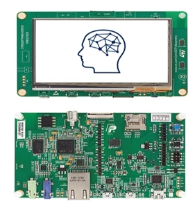
STM32 Discovery kits as well as evaluation boards include an SD card socket. While this example uses the STM32F746G-DISCO board, any other STM32 board with an SD card socket can be used. Ensure appropriate changes are made in the software configuration to accommodate a different target board.
- Hardware: STM32F746G-DISCO
- Software: STM32CubeIDE
1. Implementation steps
1.1 Create and open STM32CubeIDE project
Firstly, we need to create a STM32CubeIDE project where we configure the application to interface with the SD card.
- Open STM32CubeIDE, and create a new STM32 project, selecting the STM32F746G-DISCO template.
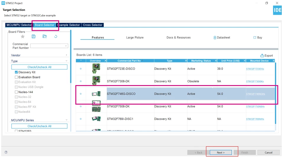
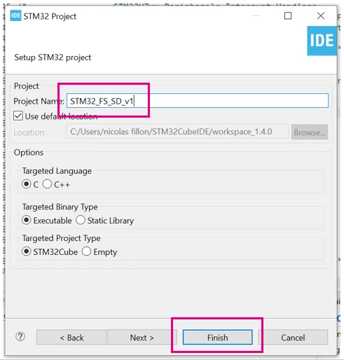
- Give a name to your project and then click finish.
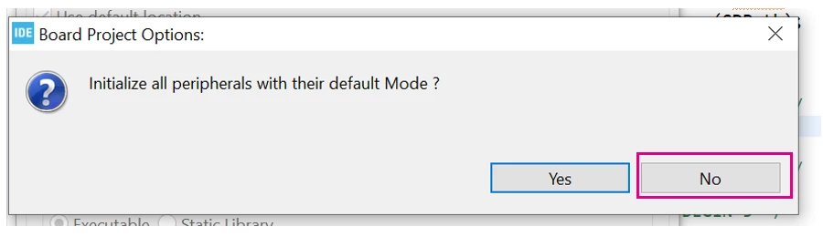
- Select [No] for the Board Project Options.
- Select [Yes] when asked to Open Associated Perspective.
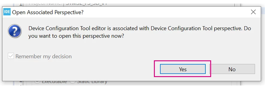
After this is done, the device configuration tool view is open in STM32CubeIDE. From here on, we can configure the MCU to be able to utilize the board's SD card slot.
2. SDMMC configuration
STM32 MCUs use the SDMMC peripheral to interface to an SD card, we need to configure it before we can write code that uses it. In this article, we also configure DMA access to the SDMMC peripheral to maximize performance.
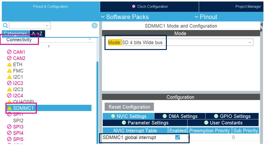
- In the Device Configuration Tool view, for the “SDMMC1” peripheral, which is located in the “Connectivity” category, set the "Mode" parameter to "SD 4 bits Wide bus".
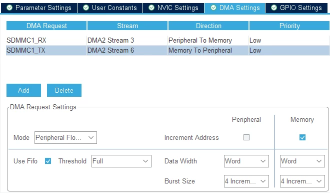
- In the DMA Settings panel, add DMA requests for SDMMC1_TX and SDMMC1_RX with their default settings.
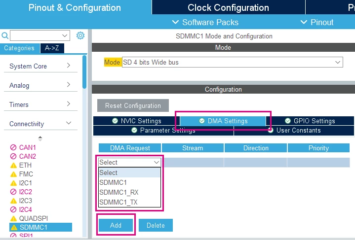
After adding these requests, the DMA settings panel should look like this:
3. FatFs configuration
FatFs is an open-source file system middleware integrated in STM32Cube libraries. It is able to directly utilize the SDMMC peripheral to act as a disk device for the FAT file system. This is also configured through the Device Configuration Tool view.
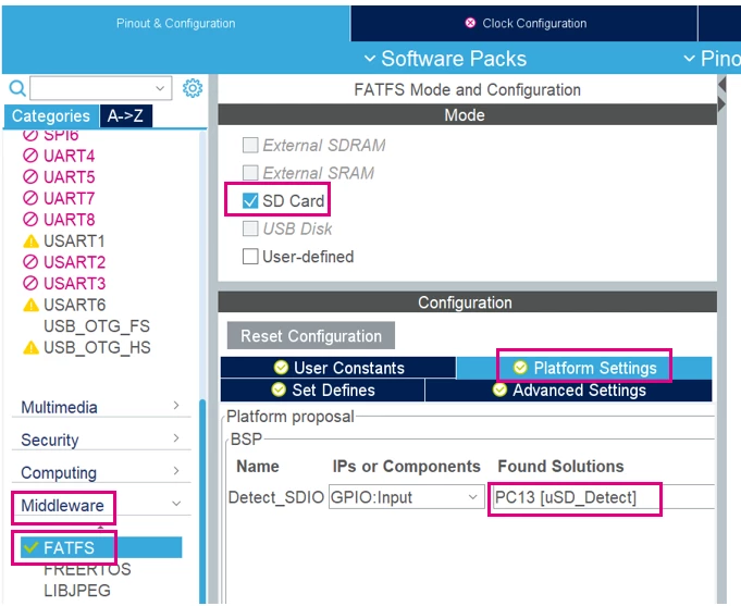
- In the "Middleware" category, for the FATFS middleware, enable the "SD card" option. In the "Platform Settings" panel, select "PC13 [uSD_Detect]" as a solution for "Detect_SDIO".
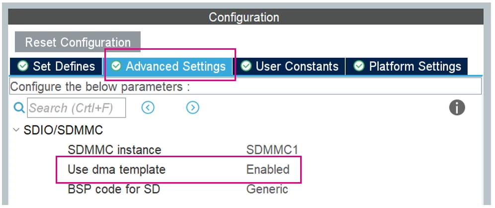
- As we are using DMA to access the SDMMC peripheral, in the "Advanced Settings" panel, enable the "Use dma template" option.
4. Project Configuration and code generation
After the peripheral and middleware configuration is complete, we will also need to modify the clock configuration and certain project settings.
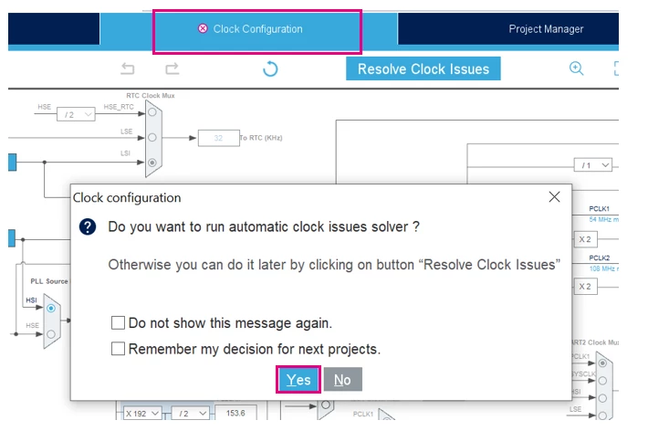
- The default clock configuration for this MCU presents an issue with the clock input to the SDMMC controller. This needs to be resolved, and can be done easily by going to the "Clock Configuration" tab and selecting [Yes] when asked to automatically resolve clock issues.
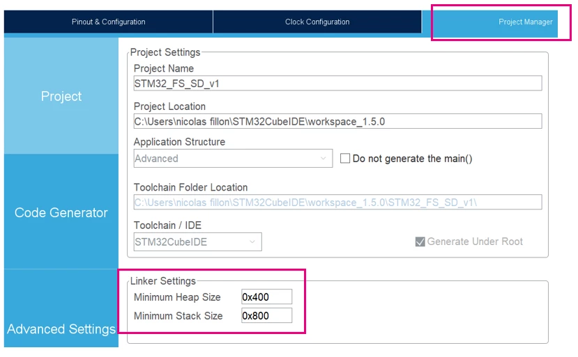
- Lastly, the FatFs middleware requires additional memory for the Heap and the Stack. In the Project Manager tab, set the "Minimum Heap Size" and "Minimum Stack Size" parameters for the Linker Settings to "0x400" and "0x800" respectively.
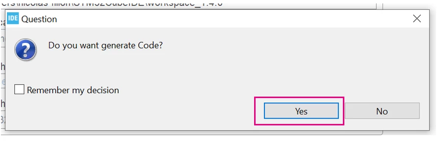
- When you save the project, the IDE presents you with an option to generate code according to your Device Configuration Tool setup. Select [Yes] when asked to generate the code.
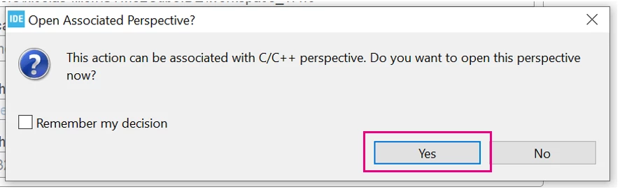
- Select [Yes] when asked to Open Associated Perspective. This will take you to your project's generated main source file.
5. Create a demo application
Now that SDMMC and FatFs configuration is complete and the appropriate code is generated, we can start writing user code that accesses the SD card. For the purposes of this article, the code sample below mounts the SD card, create a new FAT file system on it, create a file named "STM32.TXT", and write "STM32 FATFS works great!" to it.
You may copy this snippet into your main.c file - take note of the "/* USER CODE BEGIN x */" markers and place the two sections in the places that these are located in your code.
/* USER CODE BEGIN 1 */
FRESULT res; /* FatFs function common result code */
uint32_t byteswritten, bytesread; /* File write/read counts */
uint8_t wtext[] = "STM32 FATFS works great!"; /* File write buffer */
uint8_t rtext[_MAX_SS];/* File read buffer */
/* USER CODE END 1 */
 ...
/* USER CODE BEGIN 2 */
	if(f_mount(&SDFatFS, (TCHAR const*)SDPath, 0) != FR_OK)
	{
		Error_Handler();
	}
	else
	{
		if(f_mkfs((TCHAR const*)SDPath, FM_ANY, 0, rtext, sizeof(rtext)) != FR_OK)
	 {
			Error_Handler();
	 }
		else
		{
			//Open file for writing (Create)
			if(f_open(&SDFile, "STM32.TXT", FA_CREATE_ALWAYS | FA_WRITE) != FR_OK)
			{
				Error_Handler();
			}
			else
			{

				//Write to the text file
				res = f_write(&SDFile, wtext, strlen((char *)wtext), (void *)&byteswritten);
				if((byteswritten == 0) || (res != FR_OK))
				{
					Error_Handler();
				}
				else
				{

					f_close(&SDFile);
				}
			}
		}
	}
	f_mount(&SDFatFS, (TCHAR const*)NULL, 0);
/* USER CODE END 2 */
6. Build and flash the code
Finally, you may build the project and run it on the device by starting a debug session.
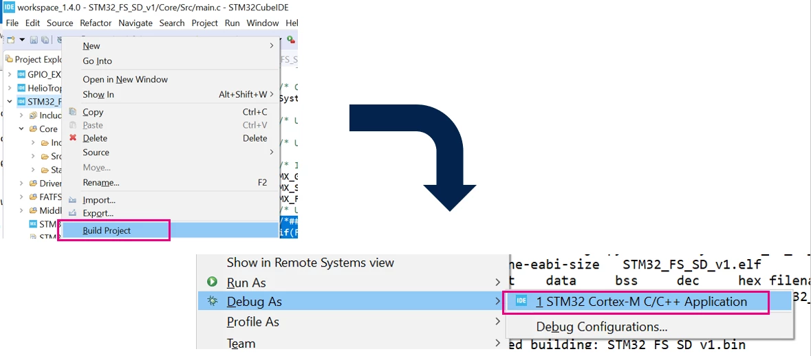
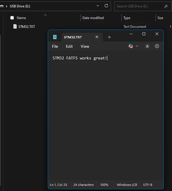 When the code is executed, the SD card is formatted and the text file is written to it. Inserting the SD card into a host PC, you may read the file, as presented in the screenshot to the right.
Related links
- STM32CubeIDE - integrated development environment for STM32 - STMicroelectronics
- FatFs - Generic FAT Filesystem Module (elm-chan.org)
Video