ST Migration account
ST Community Manager
August 22, 2026
Solved

ST25R3912-AQWT IC pinout issues and schematic validation

  • August 22, 2026
  • 3 replies
  • 11 views

150753fc-0bb7-237d-0aba-8b0d88fb2035.png

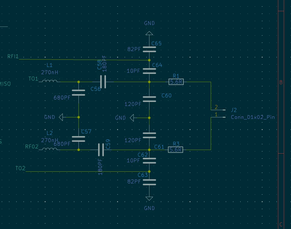
antenna tuning section 

41e8bba8-37ce-fa57-5300-75a4ace0e11a.png

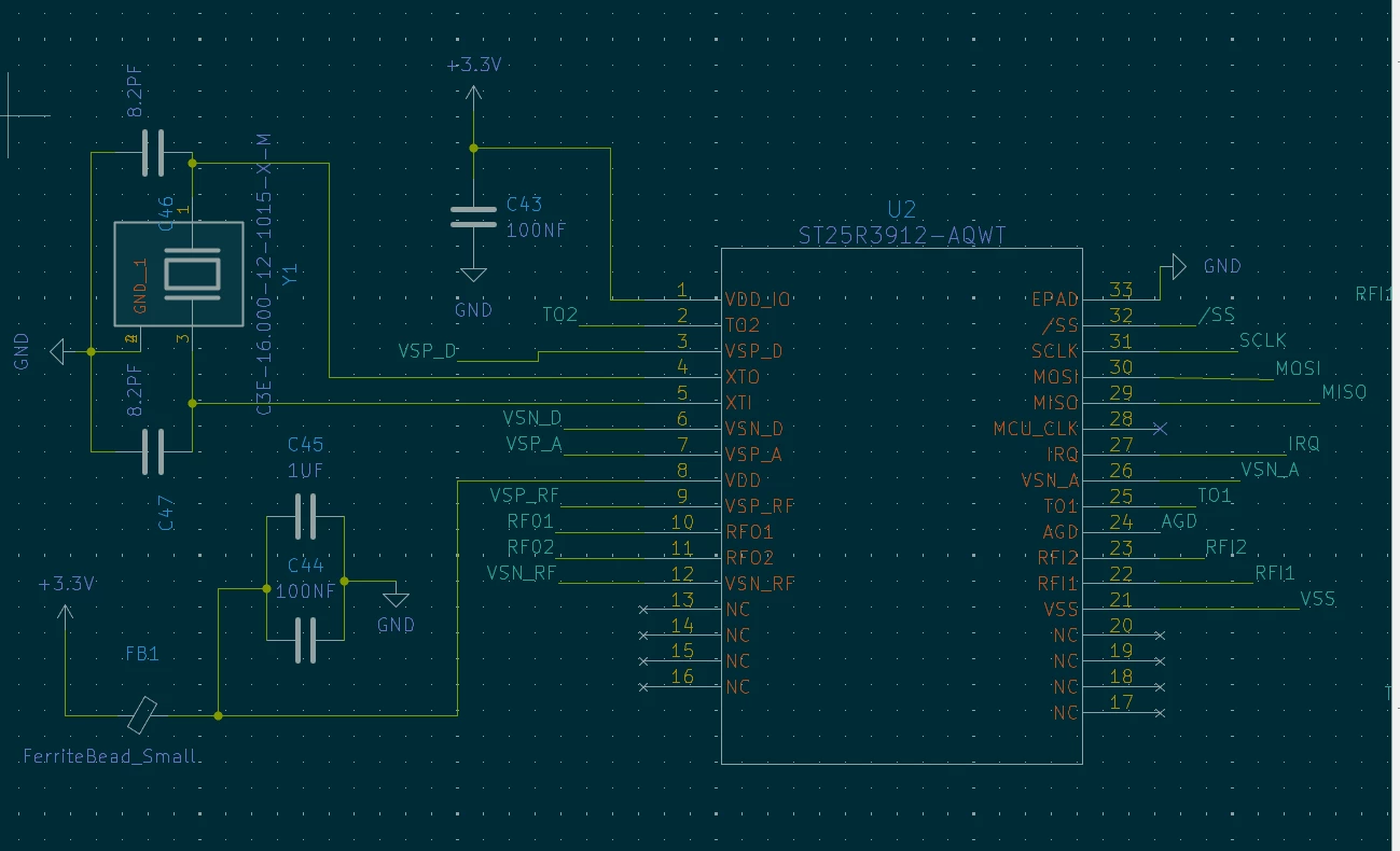
pinout is correct or not 

45b6c3a2-ac64-2d68-cd78-c22ddc42cfbc.png

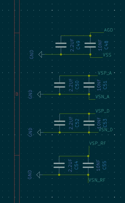
capacitor section
 

im facing issue for developing A SMART RFID reader using ST25R3912-AQWT this chip 
as per the application circuit it was mentioned RFO1 AND RFO2 are trasmitter pins but what about the TO1 AND TO2 pins can you guide me for this 
d43082bd-02cf-f03f-e5bc-1ba0d7caa58d.png

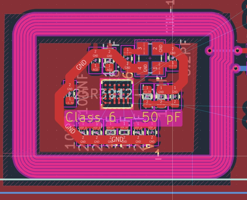
also keeping components inside the antenna is permitted or should i avoid it...? 


Best answer by Travis Palmer

Hello AKHIL_GEORGE,


the antenna tuning section is dependent on the antenna and the desired matching impedance. 

It cannot be generalized. Its values should be based on AN4974. The topology is fine.

The AGD pin requires a decoupling of 1uF // 10nF.

Having electronics inside the antenna coil causes losses (performance reduction) and the possibility to couple the 13.56MHz into the PCB traces, which can cause noise in the receiver (sensitivity loss) or EMI issues (coupling of the 13.56MHz signal into the supply lines). There should be sufficient spacing between the traces, components, planes inside the antenna and the antenna itself. 

The TO pins are TEST OUTPUT pins and not functional required. They can be used to output internal signals for debugging in case of issue. 

BR Travis 

3 replies

ST Migration account
ST Community Manager
August 22, 2026

@Travis Palmer  hai can you please help me this

This account posts content from May 22 – Jun 9 that was not included in the community migration.
Travis Palmer
Travis PalmerBest answer
ST Employee
August 22, 2026

Hello AKHIL_GEORGE,


the antenna tuning section is dependent on the antenna and the desired matching impedance. 

It cannot be generalized. Its values should be based on AN4974. The topology is fine.

The AGD pin requires a decoupling of 1uF // 10nF.

Having electronics inside the antenna coil causes losses (performance reduction) and the possibility to couple the 13.56MHz into the PCB traces, which can cause noise in the receiver (sensitivity loss) or EMI issues (coupling of the 13.56MHz signal into the supply lines). There should be sufficient spacing between the traces, components, planes inside the antenna and the antenna itself. 

The TO pins are TEST OUTPUT pins and not functional required. They can be used to output internal signals for debugging in case of issue. 

BR Travis 

ST Migration account
ST Community Manager
August 22, 2026

thank you very much Travis for the quick review and reply really appreciable

This account posts content from May 22 – Jun 9 that was not included in the community migration.