Solved
ST25DV04KC LPD Pin Voltage Anomaly (~2.1V Intermediate Level) with 4.7kΩ Pull-up Resistor
Dear ST Support Team / Community Engineers,
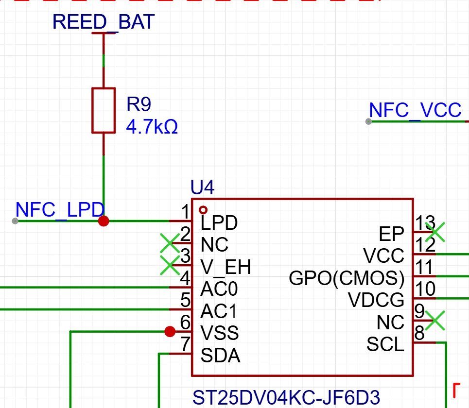
I am currently integrating the ST25DV04KC into my design. The VCC and LPD pins are connected to an MCU, which controls the transition between normal operation and ultra-low power mode.
During testing, I observed an abnormal voltage behavior on the LPD pin:
- System Voltage: 3.1V
- Pull-up Resistor: 4.7kΩ (External)
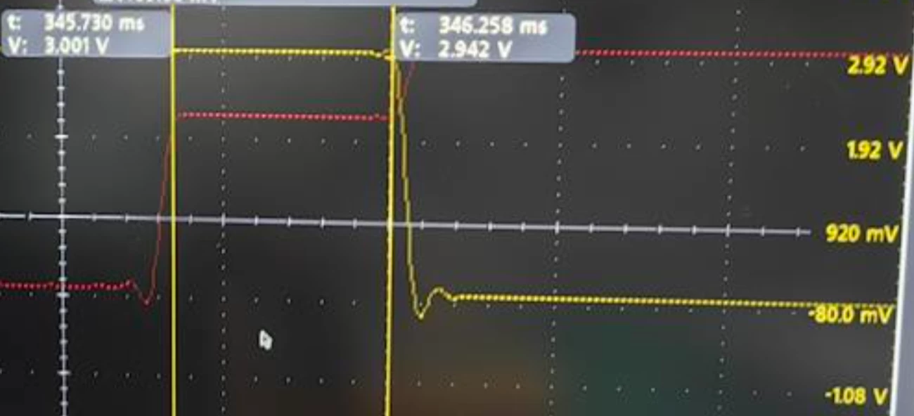
- Issue: During the level switching transition, the LPD pin voltage stalls at an intermediate level of approximately 2.1V, instead of rising cleanly to VCC. This intermediate voltage persists long enough to potentially cause logic uncertainty for the MCU.
Troubleshooting Steps Taken:
- Reduced Pull-up Resistance: I replaced the 4.7kΩ resistor with a 1.2kΩ resistor. This change successfully eliminated the intermediate voltage plateau, and the signal now transitions correctly.
- VCC Disconnection Test: I also noticed that disconnecting the VCC supply seems to eliminate this phenomenon as well.
My Questions:
- What is the physical mechanism causing this ~2.1V intermediate level when using a 4.7kΩ pull-up? Is it related to internal leakage currents or specific input threshold characteristics of the LPD pin during state transitions?
- Is the 2.1V level considered a valid high/low state, or does it pose a risk of undefined logic states for the driving MCU?
- Do you recommend a maximum pull-up resistance value for the LPD pin to ensure robust operation, especially given that 4.7kΩ seems to be borderline in this scenario?
Any insights or datasheet clarifications regarding the LPD pin's input impedance and leakage current specifications would be greatly appreciated.
Best regards,