Omar.ABDELMALEK
Associate
October 9, 2024
Solved

Raspberry Pi 3 to the STEVAL-25R3916B issue

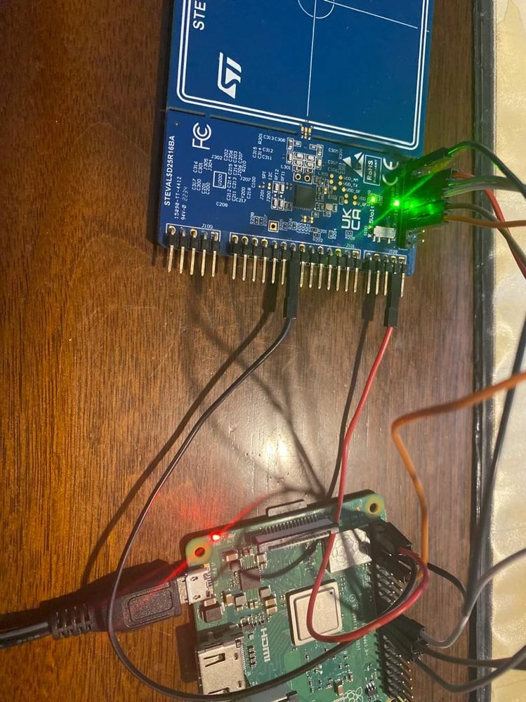
I connected a Raspberry Pi 3 to the ST25R3911B-DISCO and used the Linux driver suggested by ST.


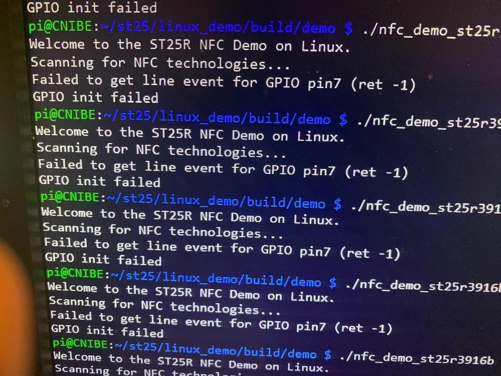
However, I haven't been able to successfully detect the IRQ despite following the setup.


1.jpg2.jpgAny suggestions on troubleshooting this issue?

This topic has been closed for replies.
Jasper Preston
Jasper PrestonBest answer
ST Employee
October 9, 2024

Hi,

I have already seen that. It happened with newer Linux kernel and SPI driver that controls by default GPIO8 for SPI0 CS0 and GPIO7 for SPI0 CS1 (e.g modinfo spidev: v5.5.61).
There is a conflict with the ST25R NFC demo that uses ST25R_INT_PIN on GPIO7 as interrupt line between the reader and the microcontroller.

To overcome this, configure the SPI driver to control a different GPIO than GPIO7 for the Chip Select signal.
This can be done with the dtoverlay command.

$ dtoverlay -a ; list all overlay available

$ dtoverlay -h spi0-1cs
Name: spi0-1cs

Info: Only use one CS pin for SPI0

Usage: dtoverlay=spi0-1cs,<param>=<val>

Params: cs0_pin GPIO pin for CS0 (default 8)
 no_miso Don't claim and use the MISO pin (9), freeing
 it for other uses.


Edit the boot configuration to use this overlay, add the following line:

$ sudo /boot/config.txt
dtoverlay=spi0-1cs
$ reboot


The parameter cs0_pin may be needed in case the driver assigns CE0 to another pin.
e.g. dtoverlay spi0-1cs,cs0_pin=6


Inspect the GPIO configuration

See http://wiringpi.com and use their convenient tool to inspect the GPIOs:

See http://wiringpi.com/ and use their convenient tool to inspect the GPIO:
$ gpio readall

 +-----+-----+---------+------+---+---Pi 4B--+---+------+---------+-----+-----+
 | BCM | wPi | Name | Mode | V | Physical | V | Mode | Name | wPi | BCM |
 +-----+-----+---------+------+---+----++----+---+------+---------+-----+-----+
 | | | 3.3v | | | 1 || 2 | | | 5v | | |
 | 2 | 8 | SDA.1 | IN | 1 | 3 || 4 | | | 5v | | |
 | 3 | 9 | SCL.1 | IN | 1 | 5 || 6 | | | 0v | | |
 | 4 | 7 | GPIO. 7 | IN | 1 | 7 || 8 | 1 | IN | TxD | 15 | 14 |
 | | | 0v | | | 9 || 10 | 1 | IN | RxD | 16 | 15 |
 | 17 | 0 | GPIO. 0 | IN | 0 | 11 || 12 | 0 | IN | GPIO. 1 | 1 | 18 |
 | 27 | 2 | GPIO. 2 | IN | 0 | 13 || 14 | | | 0v | | |
 | 22 | 3 | GPIO. 3 | IN | 0 | 15 || 16 | 0 | IN | GPIO. 4 | 4 | 23 |
 | | | 3.3v | | | 17 || 18 | 0 | IN | GPIO. 5 | 5 | 24 |
 | 10 | 12 | MOSI | ALT0 | 0 | 19 || 20 | | | 0v | | |
 | 9 | 13 | MISO | ALT0 | 0 | 21 || 22 | 0 | IN | GPIO. 6 | 6 | 25 |
 | 11 | 14 | SCLK | ALT0 | 0 | 23 || 24 | 1 | OUT | CE0 | 10 | 8 |
 | | | 0v | | | 25 || 26 | 0 | IN | CE1 | 11 | 7 | <= *: Check that 'CE1' GPIO pin 7 shows direction 'IN', to receive interrupt signal
 | 0 | 30 | SDA.0 | IN | 1 | 27 || 28 | 1 | IN | SCL.0 | 31 | 1 |
 | 5 | 21 | GPIO.21 | IN | 1 | 29 || 30 | | | 0v | | |
 | 6 | 22 | GPIO.22 | IN | 1 | 31 || 32 | 0 | IN | GPIO.26 | 26 | 12 |
 | 13 | 23 | GPIO.23 | IN | 0 | 33 || 34 | | | 0v | | |
 | 19 | 24 | GPIO.24 | IN | 0 | 35 || 36 | 0 | IN | GPIO.27 | 27 | 16 |
 | 26 | 25 | GPIO.25 | IN | 0 | 37 || 38 | 0 | IN | GPIO.28 | 28 | 20 |
 | | | 0v | | | 39 || 40 | 1 | IN | GPIO.29 | 29 | 21 |
 +-----+-----+---------+------+---+----++----+---+------+---------+-----+-----+
 | BCM | wPi | Name | Mode | V | Physical | V | Mode | Name | wPi | BCM |
 +-----+-----+---------+------+---+---Pi 4B--+---+------+---------+-----+-----+


*: Check that 'CE1' GPIO pin 7 shows direction 'IN', to receive interrupt signal


Hope this helps.

Br,

Jasper

3 replies

Ulysses HERNIOSUS
ST Technical Moderator
October 9, 2024

Hi,


well, you are not showing a ST25R3911B-DISCO but a STEVAL-2543916B board. 

The error message you are getting indicates that in your system somebody else uses the GPIO7. This should also happen without the 3916B board connected. I think you need to look on your Linux to see the usage of the different GPIOs.

BR, Ulysses

Omar.ABDELMALEK
Associate
October 9, 2024

i have install new image in my rasp without any other program 

Jasper Preston
Jasper PrestonBest answer
ST Employee
October 9, 2024

Hi,

I have already seen that. It happened with newer Linux kernel and SPI driver that controls by default GPIO8 for SPI0 CS0 and GPIO7 for SPI0 CS1 (e.g modinfo spidev: v5.5.61).
There is a conflict with the ST25R NFC demo that uses ST25R_INT_PIN on GPIO7 as interrupt line between the reader and the microcontroller.

To overcome this, configure the SPI driver to control a different GPIO than GPIO7 for the Chip Select signal.
This can be done with the dtoverlay command.

$ dtoverlay -a ; list all overlay available

$ dtoverlay -h spi0-1cs
Name: spi0-1cs

Info: Only use one CS pin for SPI0

Usage: dtoverlay=spi0-1cs,<param>=<val>

Params: cs0_pin GPIO pin for CS0 (default 8)
 no_miso Don't claim and use the MISO pin (9), freeing
 it for other uses.


Edit the boot configuration to use this overlay, add the following line:

$ sudo /boot/config.txt
dtoverlay=spi0-1cs
$ reboot


The parameter cs0_pin may be needed in case the driver assigns CE0 to another pin.
e.g. dtoverlay spi0-1cs,cs0_pin=6


Inspect the GPIO configuration

See http://wiringpi.com and use their convenient tool to inspect the GPIOs:

See http://wiringpi.com/ and use their convenient tool to inspect the GPIO:
$ gpio readall

 +-----+-----+---------+------+---+---Pi 4B--+---+------+---------+-----+-----+
 | BCM | wPi | Name | Mode | V | Physical | V | Mode | Name | wPi | BCM |
 +-----+-----+---------+------+---+----++----+---+------+---------+-----+-----+
 | | | 3.3v | | | 1 || 2 | | | 5v | | |
 | 2 | 8 | SDA.1 | IN | 1 | 3 || 4 | | | 5v | | |
 | 3 | 9 | SCL.1 | IN | 1 | 5 || 6 | | | 0v | | |
 | 4 | 7 | GPIO. 7 | IN | 1 | 7 || 8 | 1 | IN | TxD | 15 | 14 |
 | | | 0v | | | 9 || 10 | 1 | IN | RxD | 16 | 15 |
 | 17 | 0 | GPIO. 0 | IN | 0 | 11 || 12 | 0 | IN | GPIO. 1 | 1 | 18 |
 | 27 | 2 | GPIO. 2 | IN | 0 | 13 || 14 | | | 0v | | |
 | 22 | 3 | GPIO. 3 | IN | 0 | 15 || 16 | 0 | IN | GPIO. 4 | 4 | 23 |
 | | | 3.3v | | | 17 || 18 | 0 | IN | GPIO. 5 | 5 | 24 |
 | 10 | 12 | MOSI | ALT0 | 0 | 19 || 20 | | | 0v | | |
 | 9 | 13 | MISO | ALT0 | 0 | 21 || 22 | 0 | IN | GPIO. 6 | 6 | 25 |
 | 11 | 14 | SCLK | ALT0 | 0 | 23 || 24 | 1 | OUT | CE0 | 10 | 8 |
 | | | 0v | | | 25 || 26 | 0 | IN | CE1 | 11 | 7 | <= *: Check that 'CE1' GPIO pin 7 shows direction 'IN', to receive interrupt signal
 | 0 | 30 | SDA.0 | IN | 1 | 27 || 28 | 1 | IN | SCL.0 | 31 | 1 |
 | 5 | 21 | GPIO.21 | IN | 1 | 29 || 30 | | | 0v | | |
 | 6 | 22 | GPIO.22 | IN | 1 | 31 || 32 | 0 | IN | GPIO.26 | 26 | 12 |
 | 13 | 23 | GPIO.23 | IN | 0 | 33 || 34 | | | 0v | | |
 | 19 | 24 | GPIO.24 | IN | 0 | 35 || 36 | 0 | IN | GPIO.27 | 27 | 16 |
 | 26 | 25 | GPIO.25 | IN | 0 | 37 || 38 | 0 | IN | GPIO.28 | 28 | 20 |
 | | | 0v | | | 39 || 40 | 1 | IN | GPIO.29 | 29 | 21 |
 +-----+-----+---------+------+---+----++----+---+------+---------+-----+-----+
 | BCM | wPi | Name | Mode | V | Physical | V | Mode | Name | wPi | BCM |
 +-----+-----+---------+------+---+---Pi 4B--+---+------+---------+-----+-----+


*: Check that 'CE1' GPIO pin 7 shows direction 'IN', to receive interrupt signal


Hope this helps.

Br,

Jasper