Associate
June 12, 2026
Question

M24LR16E-R RF Read/Write issue

  • June 12, 2026
  • 13 replies
  • 176 views

Hello Team,

I am facing RF read and write issues with the M24LR16E‑R EEPROM.

The exact problem is as follows:

  • When I take a new EEPROM and write data to it using an RF NFC reader for the first time, the operation is successful.
  • However, during subsequent attempts to read and write:
    • In some EEPROMs, RF read works but write fails but I2C read/Write working.
    • In some devices, both read and write operations fail but I2C read/Write working.
    • A few EEPROMs work correctly without any issues.

In our application, we are using Sector 2 and Sector 3 for user data storage.

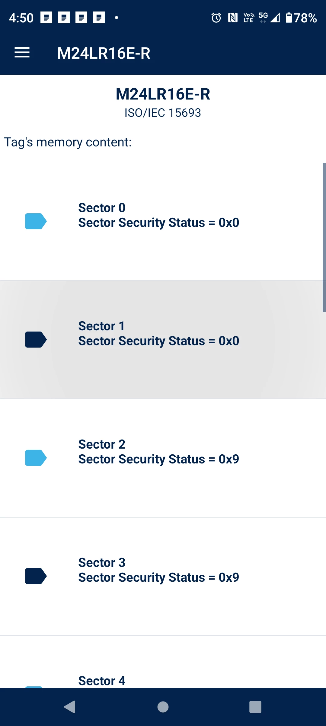
When I read data from the problematic EEPROMs through St25 mobile application, I observe the following:

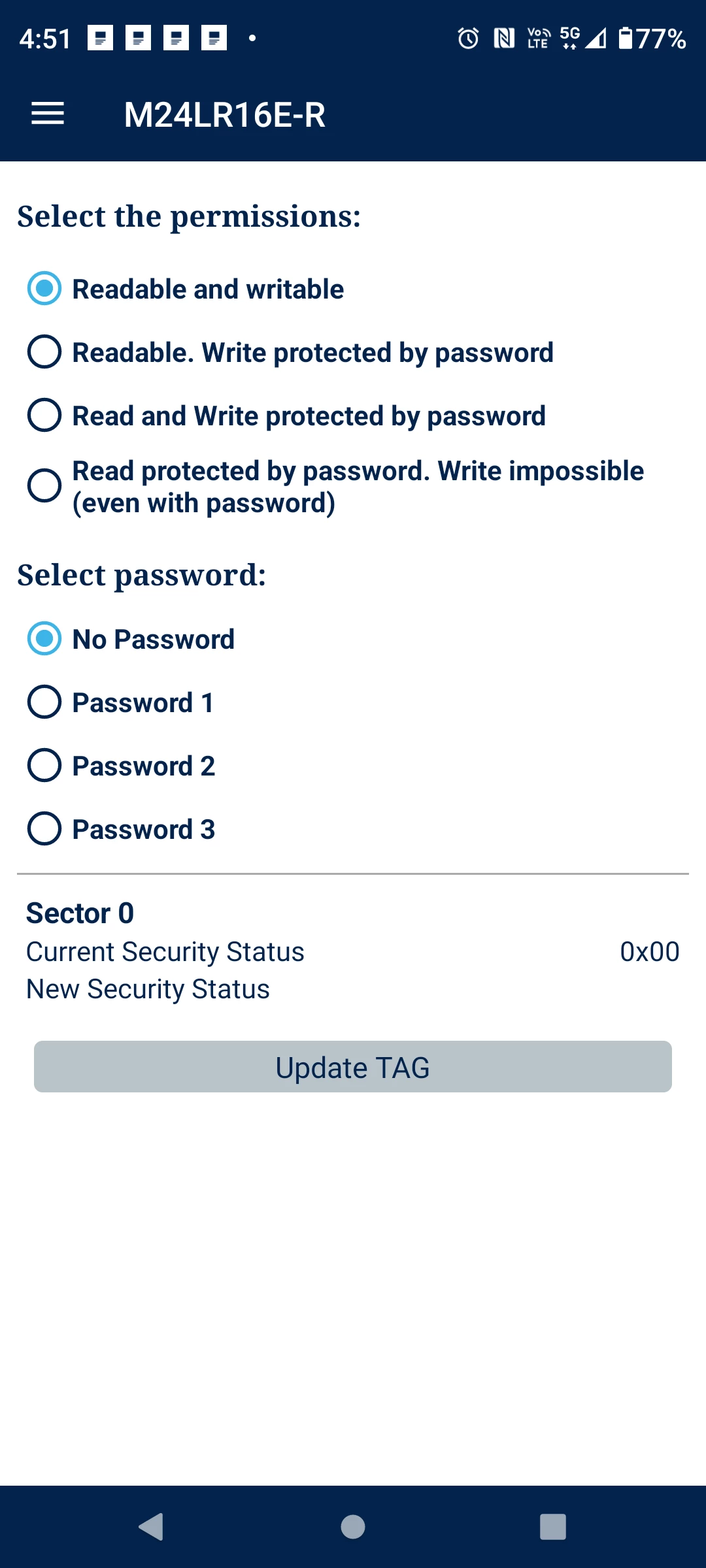
  • Sector 0 and Sector 1 Security Status is 0x00. And the data read and write is working in these 2 sectors.
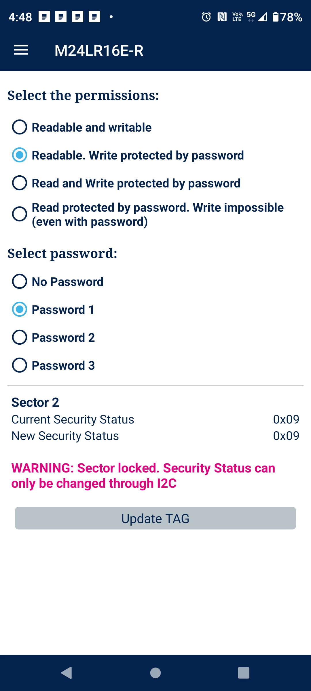
  • Sector 2 to Sector 15 Security status:
    • Current Security Status: 0x09
    • New Security Status: 0x09

Additionally, I receive the warning:

“Sector locked. Security Status can only be changed through I2C.”

I am not sure why the security status has changed or why the sectors are locked.

Could you please provide clarification on the following points?

  1. Is it possible to unlock the EEPROM once it is locked?
  2. Can the EEPROM be unlocked via RF (NFC reader), or is I2C the only method?
  3. What could be the possible causes for the EEPROM sectors getting locked in this scenario?


Thanks,

Naveen 
 

13 replies

JL. Lebon
ST Employee
June 16, 2026

Hello, 

It is possible to unlock a sector, but only from the I2C interface. Once locked, a sector cannot be unlocked from the RF interface,

To unlock the sector, the I2C password must first be presented, then it is possible to write in the system area from I2C to unlock the sector.

There is no clue in what you describe that can explain why those sectors become locked. Most probably a lock-sector RF command has been issued at some point, or the sector security status byte has been programmed from I2C at some point. If you describe more your setup and what you are doing with the tag it may help understanding.

Best regards.


Associate
June 18, 2026

Hello,

Thank you for your response.

Let me explain our setup in detail to help identify the issue:

We are using motors equipped with NFC-enabled M24LR16E‑R tags. The EEPROM is programmed using an NFC programmer, and in our application, we are specifically using Sector 2 and Sector 3 for user memory storage.

Recently, we observed that these sectors are not writable through the NFC interface (RF). Based on your explanation, it appears that the sectors might have been locked, possibly due to:

  • An unintended lock-sector RF command, or
  • Accidental modification of the Sector Security Status (SSS) bytes via I²C

At this point, we are trying to understand:

  1. What could be causing these sectors (2 and 3) to become locked in our use case where only NFC programming is intended
  2. Whether the NFC programming tool itself could be issuing a lock command unintentionally
  3. How to confirm definitively (via I²C) if the sector is:
    • Permanently locked, or
    • Password/write-protected but recoverable

We are planning to access the device over I²C to:

  • Present the I²C password (if required)
  • Attempt to clear the SSS configuration and restore write access

If you have any guidance on:

  • Specific registers or bits to check to confirm lock status
  • Recommended safe configuration for sectors used only for NFC writable memory

that would be very helpful.

Looking forward to your suggestions.

Best regards,
Naveen

JL. Lebon
ST Employee
June 18, 2026

Hello, 

Thank you for the explanation.

To access the SSS configuration from I2C you can:

Read the SSS from I2C:

  • the device select code must be with E2=1: 0xAE/AF
  • the memory address of the SSS starts at 0x0000 (SSS0 sector 0), 0x0001 (SSS1 sector 1), 0x0002 (SSS2 sector 2) and 0x0003 (SSS3 sector 3), etc…
  • Example to read the SSS3 of sector 3: Start/0xAE/0x00/0x03/Restart/0xAF/SSS3/Stop

If bit 0 (Sector lock) is set, it means that the sector is protected. The bits 2 and 1 determine the type R/W of protection and the bits 4 and 3 determine the password used to protect.

Write the SSS from I2C:

  • Example to write all bits to 0 for SSS1: Start/0xAE/0x00/0x01/0x00/Stop

Best regards, 

Jean-louis

Associate
June 19, 2026

Hello,

Thank you for the detailed explanation. It was very helpful.

Based on your guidance, I was able to understand the SSS configuration and successfully unlock the sectors using I²C commands. After unlocking, I am also able to read and write the memory using the ST25 mobile application via NFC without any issues.

However, in our application, we are using a custom tool to program the EEPROM through an NFC programmer. When I attempt to perform read/write operations using this tool over RF, I observe that the sectors are getting locked again automatically. This behavior is occurring specifically during RF read/write operations.

I am unable to identify the root cause of this issue. Could you please help clarify the following:

  • What are the possible conditions under which sectors can get locked again during RF operations?
  • Is it possible that any RF write operation (intentional or unintended) is modifying the SSS configuration?
  • Can there be any conflict or side effects when using I²C and RF interfaces (NFC) alternately or simultaneously?

Additionally, I have one observation:
For both working EEPROMs and those where write fails or sectors appear locked, the sector status (SSS) is showing 0x09. Since the SSS value is the same in both cases, I am unable to understand why the RF write is failing even when the sector status appears identical.

Your guidance will help us understand and resolve this issue.

Best regards,
Naveen

JL. Lebon
ST Employee
June 19, 2026

Hello,

I’m glad my comments have been helpful.

Actually, the sectors can be locked in two ways:

  • from RF: using the Lock-sector command (code B2)
  • from I2C: you must first present the I2C password, then writing in the system memory (device select code 0xAE) at the address of the SSS.

Those are the two ways of locking sectors. there is no effect or side effect of simultaneous or alternate I2C /RfF commands.

I guess that during your process, a Lock-sector command is sometime issued, or the I2C is writing the SSS, difficult to say. 
If you have a trace of all RF command sent by your application, you can search for an RF command with command code 0xB2.

As for your last question, I assume that you are able to write in EEPROMs with SSS=0x09 because somehow the correct Present sector password command has been issued at some point (command code 0xB3). Once the correct password has been presented (here with SSS-0x09 it should be password 0x01), the security session is opened and the write is possible.

Best regards.

Associate
June 22, 2026

Hello,

Thank you for the detailed explanation. It is very helpful.

Based on your inputs, I understand that sectors can only be locked either through the RF interface using the 0xB2 (Lock Sector) command or through the I²C interface by writing to the SSS after providing the password. In my case, there is currently no issue from the I²C side, and the sector locking is occurring only during RF operations.

I will check the RF command trace from our application and specifically look for any unintended 0xB2 (Lock Sector) command being issued during the programming sequence.

Regarding the SSS value (0x09), your explanation clarifies that the write operation is possible when the correct Present Password command (0xB3) has already been issued, opening a secure session. This helps explain the intermittent write success observed in our testing.

I will analyze the RF communication logs in our tool and verify if any unintended lock command is being triggered during read/write operations.

Thank you for your support.

Best regards,
Naveen

Associate
July 2, 2026

Hello,

Is there any possibility to read RF Password 1, RF Password 2, and RF Password 3 using an I2C interface or an RF device?

Best regards,

Naveen Kongari

JL. Lebon
ST Employee
July 2, 2026

Hello, 

Unfortunately (or fortunately for security reasons) it is not possible to read the passwords values, neither from RF interface nor from I2C interface.

Best reagrds.

Associate
July 2, 2026

Hello,

Thank you for the clarification. I understand that reading the actual RF password values is not allowed for security reasons.

However, during my testing, I attempted to read RF Password 1, RF Password 2, and RF Password 3 through the I2C interface and received a value of 0xFFFFFFFF for each password location. I assume this is a placeholder value and not the actual password.

I have one additional question:

if the RF password is forgotten or lost, is there any method to recover or reset it? If recovery is not possible, would the RF-protected functionality become permanently inaccessible, effectively making that portion of the EEPROM unusable?

Thank you for your support.

Best regards,
Naveen Kongari


JL. Lebon
ST Employee
July 2, 2026

Hello, 

The 0xFFFFFFF value you read through the i2C is the result of the I2C bus architecture: the SDA line is open-drain and pulled-up to VCC through a pull-up resistor. So if no I2C device drives the line to low, the signal is always high and data is read as 0xFF. This is what happens when you try to read the password: the ST25DV doesn’t return data and the line is read at 0xFF thanks to the pull-up.

There is no way to reset any of the passwords. If a password is lost, it is not possible to recover it other than guessing, which may take very long…

If you have a portion of the EEPROM protected by a forgotten RF password for RF access, you can still unprotect it if you know the I2C password, since after presenting the I2C password you can change the SSS value from I2C interface.

Best regards.

Associate
July 3, 2026

Hello,

Thank you for the detailed explanation.

Could you please provide information on the communication protocol used by the M24LR16E-R EEPROM?

Specifically, I would like to understand:

  • The protocol required for EEPROM read and write operations.
  • The command frame structure for read and write accesses.
  • Any details regarding addressing (device address, memory address format, etc.).
  • Example command frames for reading and writing data.

This information will help us better understand the communication flow and debug our implementation.

Thank you for your support.

Best regards,
Naveen Kongari

JL. Lebon
ST Employee
July 3, 2026

Hello, 

Are you talking about read and write access from the RF interface or from the I2C interface ?

Best regards.

Associate
July 3, 2026

Hello,

I am taking about the read and write access from the RF interface.


Thanks.