

Solved
EMI filter for CR95HF and more
Hello,
I am making a project with CR95HF on a custom PCB and I have been researching some information about the antenna for the transceiver operated by the early mentioned chip. I have couple questions to clear up your documentations for CR95HF and X-NUCLEO-NFC03A1.
- In the documentation AN5248, you mention in the calculation for EMI cut-off frequency that fc= 1 / 2*PI*sqrt[(2*L0) * (C0/2)] = 14.6 MHz, however my calculation brought me a result of fc = 15.04 MHz. What causes this almost 0.5 MHz jump?
- In the same document AN5248, you use this drawing of schematic part close to antenna:
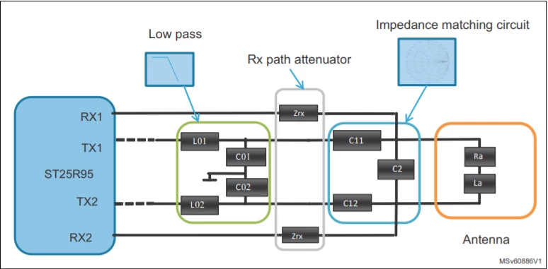 There you mention Low pass filter contains 2 capacitors, C01 and C02, that are equal in value. However in the schematic of X-NUCLEO-NFC03A1 (for example UM2479), there are 4 capacitors in parallel (C9, C10, C13 and C14).
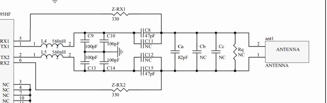 What is the difference between using 2 and 4 capacitors in the EMI filter. According to the fc formula, it should not change the cut-off frequency so I have been wondering what is the purpose of doubling them in parallel?
 - Last question I have been wondering about is that in the CR95HF Antenna Design Query post that was made earlier you mentioned that X-NUCLEO-NFC03A1 antenna is 34x47mm/4 turns/0.8ohm~1120nH antenna. I downloaded the gerber files and put the parameters into your eDesign suite to come up with inductance result of 1260 nH.
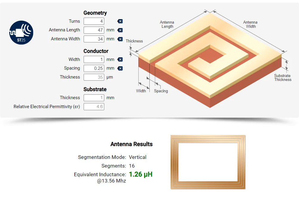 Could that difference be caused by rounded corners of the actual antenna on X-NUCLEO-NFC03A1, while the design suite counts with "perfect" rectangle? Or there is a difference because of "theory versus the real thing" reason? Or possibly something else?
I have to design a multiple antennas on a custom PCB and test their functions, so I am trying to clear up the information about EMI and antenna design, before actually designing the prototypes. Thank you so much for help and clarification!
