Jens_
Associate II
January 12, 2021
Question

STML011 temperature sensor accuracy

  • January 12, 2021
  • 10 replies
  • 5484 views

Hi,

I am having problems measuring accurate temperatures with the internal temperature sensor of the STM32L011D4P7 over the full device temperature range of -40 °C to 130 °C.

What I did: Measuring the temperature as described in the Reference Manual (RM0377), Chapter 13.9 "Reading the temperature" which mentions the code example A.8.17.

There are two temperature calibration values TS_CAL1 and TS_CAL2 mentioned and used.

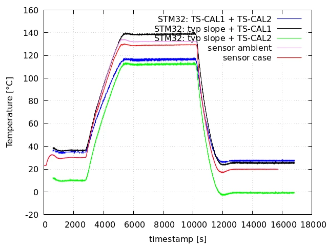
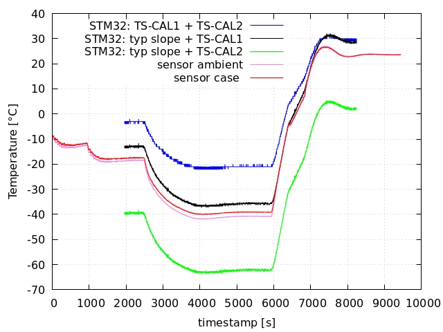
The two images show temperature measurements I did in a climatic chamber. The STM32 internal measurement (purple) is done as described above. Two external temperature sensors (green) controlled by additional testing hardware (not the STM32) are used to measure the ambient temperature and the case temperature on top of the STM32.

Calculation values:

Read out Calibration values from STM32 at the addresses mentioned in the example code:

TS_CAL1: 662

TS_CAL2: 940

Measured example values:

external temperature sensor in the climatic chamber:

-40 °C | 30 °C | 130 °C

meaured STM32 ADC raw value (VDDA = 3.3 V):

469 | 613 | 817

STM32 internal temperature calculated as described in A.8.17 from ADC raw values:

-21 °C | 35 °C | 117 °C

Measurements in the climatic chamber:

  • x-axis: timestamp in seconds
  • y-axis: temperature in °C
  • The STM32 measurements are using the named values for calculation
 0693W000007BaQ0QAK.png0693W000007BaQ5QAK.pngMeasurement evaluation:

  • The measurements show an error of 19 °C at -40 °C ambient temperature, 5 °C error at 35 °C and 13 °C error at 130 °C.
  • black curve: when using the TS_CAL1 value (which is not mentioned in the datasheet and can/should not be used!) with the average slope from the datasheet the curve seems realistic
  • green curve: when using only the specified data from the datasheet, which is TS_CAL2 and average slope, the temperature does not make sense

Finally my questions:

  1. Can anyone confirm/disconfirm the measurement deviation?
  2. Can anyone confirm my implemented calculation by checking the given "measured example values"?
  3. Can I generally expect correct temperature values (approx. +/- 4 °C accuracy) over the whole temperature range of the given STM32L011D4P7 device?
  4. Is it allowed to use the TS_CAL1 value as done in the code example A.8.17, although TS_CAL1 is NOT mentioned in the Datasheet?

EDIT:

  • update temperature plots

Many greetings

Jens

This topic has been closed for replies.

10 replies

Uwe Bonnes
Chief
January 12, 2021

stm32l0xx_ll_adc. tells: /* Note: On device STM32L011, calibration parameter TS_CAL1 is not available. */

That's what you get from selecting the cheapest part!. So you have to either set up an environment to measure it yourself and track them on a per part base or select a part that exports TS_CAL1.

Jens_
Jens_Author
Associate II
January 13, 2021

Yes the goal is to select the cheapest part... for obvious money reasons.

Good to know that only the generated code explicitly excludes the TS_CAL2 value while the code example in the documentation uses it!

The datasheet in the STM32xx is very short in terms of the temperature sensor. In other projects (with more expensive STM32s) the temperature measurement works just fine.

So can i generally assume if I want a precise temperature measurement I have to take a STM32 that has both calibration values?

waclawek.jan
Super User
January 12, 2021

Did you perform ADC calibration as per Calibration (ADCAL) subchapter of ADC chapter of RM?

Against what reference are you measuring (i.e. is VDDA precise and stable throught the whole temperature range - I assume given mcu does not have separate VREF+ pin?)

JW

Jens_
Jens_Author
Associate II
January 13, 2021

Yes I did.

Yes the smallest package is used where the VDDA is the same pin as VREF+.

The VDDA is determined by measuring the internal reference V_REFINT as the reference manual states in Chapter 13.9 "Calculating the actual VDDA ..." every time before measuring the temperature.

-Jens

waclawek.jan
Super User
January 13, 2021

Don't you try to do this after sleep/wakeup or in continuously runing mcu?

Make sure you observe internal voltage reference and thermometer startup and sampling times.

Can you measure VDDA independently?

How do you remove readout noise?

Analyze discrepancy between stored and measured really values. The one guaranteed by the DS should match closely.

Do you have multiple specimens, perhaps also something like a Nucleo board?

JW

Jens_
Jens_Author
Associate II
January 15, 2021

Sorry for the late response, could not log in to my ST account..

In this case the STM32 was always in run mode.

In the final application the MCU will have a sleep/run cycle. But the temp sensor will not be turned off. In my understanding it is therefore not necessary to wait for the startup time.

I did a independent VDDA measurement. The values seemed to be fine, although changing over temperature.

No care is taken of the readout noise. The measurement error does more look like some kind of gain error.

The calibration value TS_CAL2 mentioned in the datasheet matches the given tolerance on multiple boards.

I do have multiple nucleo boards with similar MCU, but only did some table measurements not in a climatic chamber. Behaviour seemed to be very similar to the detailed measurement.

-Jens

waclawek.jan
Super User
January 15, 2021

>> How do you remove readout noise?

> No care is taken of the readout noise.

I am asking because on the upper figure, the green and purple appear to meet at cca 30 deg. on the upward slope, but significantly higher, at cca 70 deg, on the downward slope.

So if this is not result of some filtering (i.e. processing the output of ADC, possibly introducing lags or some other errors), then I'd question the relevance of measuring the "green" temperatures for determining the internal temperature of the chip. In other words, temperature of "ambient" and "case" might be very different from internal temperature of the chip, possibly for incorrect methodology of measuring the former two (e.g. there's a significant thermal path between the chip and 20deg exterior, as compared to the termal path between "ambient"/"case" to chip.)

JW

Jens_
Jens_Author
Associate II
January 15, 2021

I get your point. I have a simple explanation for the different temperatures at the intersections: The external sensor values and the internal measurement have different time bases and have been put together afterwards. The STM32 might count little too fast or slow in comparism to the real time.

Yes the external temperatures do not show the exact internal temperature. Still both internal+external should have the same trend and I would expect a nearly constant offset over the temperature range. Additionally I can not think of another way checking the temperature..

Uwe Bonnes
Chief
January 15, 2021

As I wrote before, there is no TS_CAL1 and to get sensible results you have to aquire this value yourself. The curves you supply have decnet tracking of temperature changes, for me. only calibration values seem off.

Jens_
Jens_Author
Associate II
January 18, 2021

Aquiring a calibration value myself is not an option because this is for a series product.

Yes I agree with you. The tracking of the curves seem fine. Only the calibration TS_CAL2 seems to be off.

The generated code states there is no TS_CAL1. But in the address used in the code example there is an value which looks very much like the TS_CAL1 value.

I was playing with the calibration values. The TS_CAL1 + the average slope of the temperature sensor actually gives a temperature curve which looks realistic! (I udpated this in the plots above)