STM32H745 problem with SPI in DMA and DMAMUX synchronization with LPTIM2
Hello,
I'm working on a board with STM32H745. The mcu has to interface with an external ADC
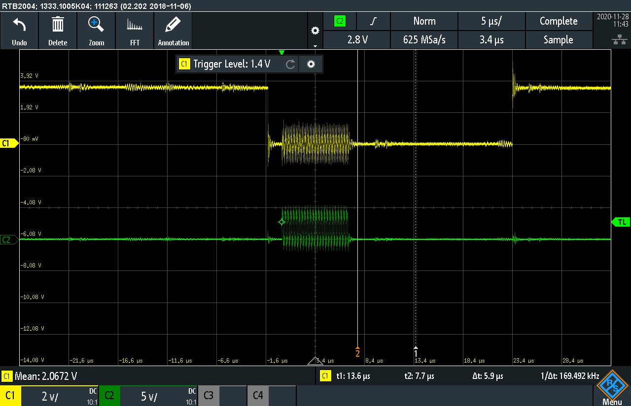
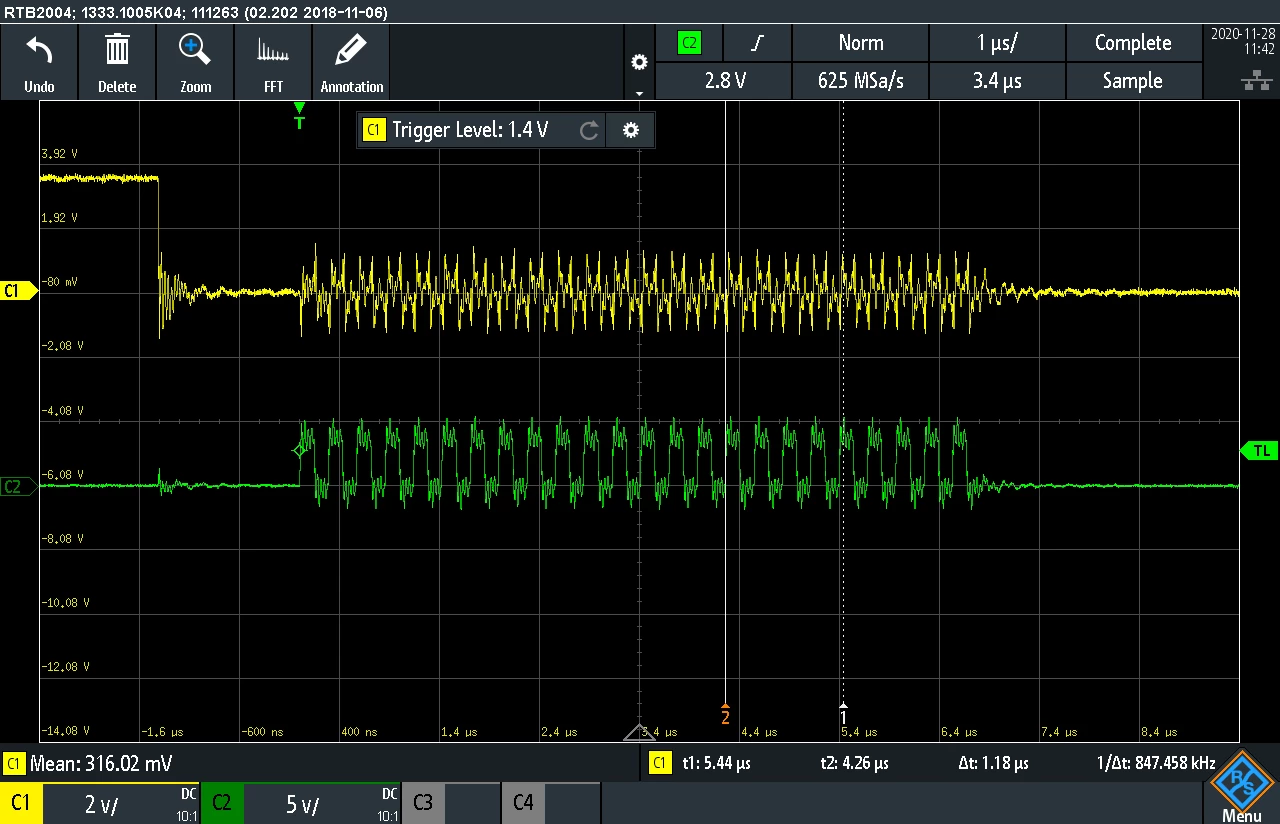
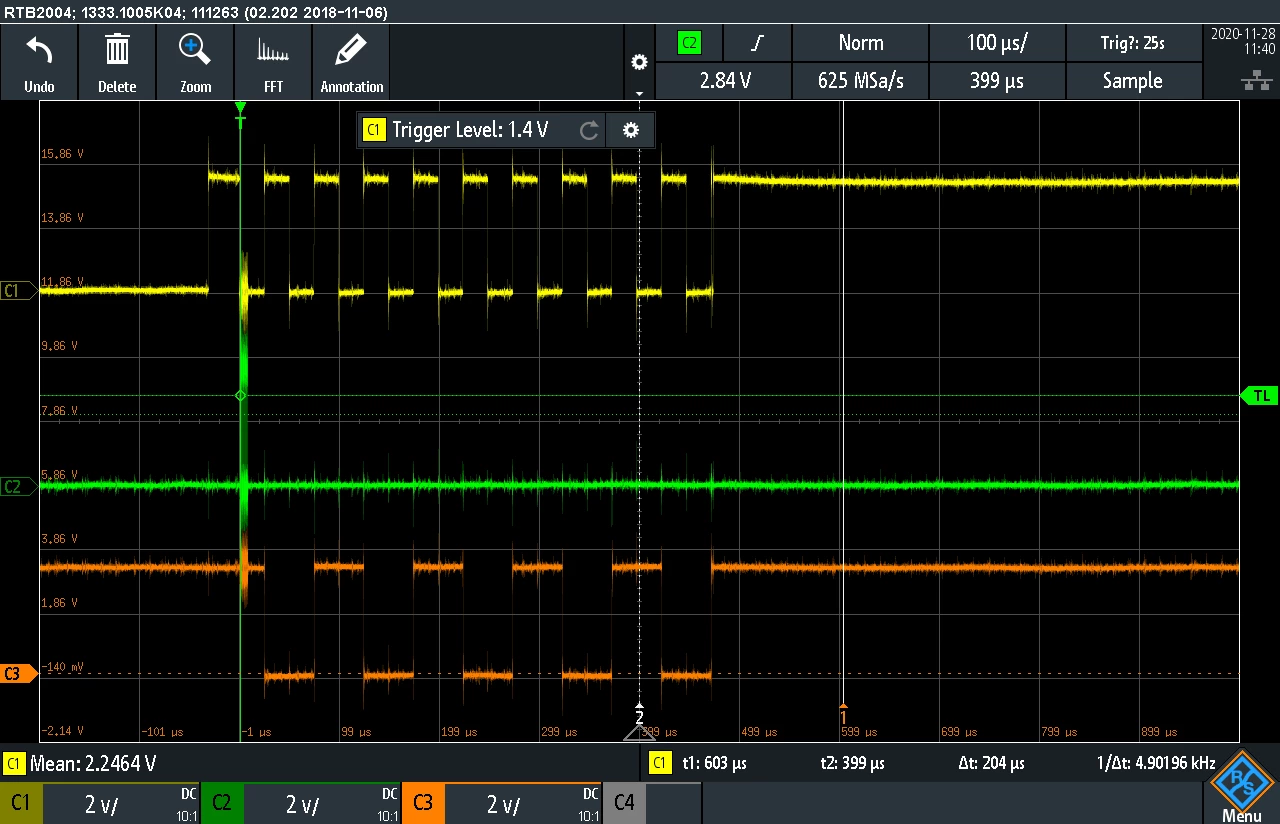
(LTC2335-16) to permit a max sample rate of 1M/s (during software develop 20KHz see images).
So, i've decide to use LPTIM2 to generate the 1MHz signal (50% duty) to generate the
start conversion for ADC (positive edge). After 500nsec the converted data is ready to
get out the 3 bytes read (see the attached images). So I configure the SPI with transmit and
receive DMA with the synchronization event for DMA TX with the falling edge of LPTIM2 signal.
Here is the peripheral initialization software.
 SpiHandle.Instance = SPI4;
 SpiHandle.Init.MasterKeepIOState = SPI_MASTER_KEEP_IO_STATE_ENABLE; // Recommended setting to avoid glitches
 SpiHandle.Init.Mode = SPI_MODE_MASTER;

 SpiHandle.Init.BaudRatePrescaler = SPI_BAUDRATEPRESCALER_32; //SPI_BAUDRATEPRESCALER_128,
 SpiHandle.Init.Direction = SPI_DIRECTION_2LINES;

 SpiHandle.Init.CLKPhase = SPI_PHASE_1EDGE;
 SpiHandle.Init.CLKPolarity = SPI_POLARITY_LOW;

 SpiHandle.Init.DataSize = SPI_DATASIZE_8BIT;
 SpiHandle.Init.FirstBit = SPI_FIRSTBIT_MSB;
 SpiHandle.Init.TIMode = SPI_TIMODE_DISABLE;

 SpiHandle.Init.NSS = SPI_NSS_HARD_OUTPUT;
 SpiHandle.Init.NSSPMode = SPI_NSS_PULSE_ENABLE;
 SpiHandle.Init.NSSPolarity = SPI_NSS_POLARITY_LOW;

 SpiHandle.Init.CRCCalculation = SPI_CRCCALCULATION_DISABLE;
 SpiHandle.Init.CRCPolynomial = 7;
 SpiHandle.Init.CRCLength = SPI_CRC_LENGTH_8BIT;

 SpiHandle.Init.TIMode = SPI_TIMODE_DISABLE;

 if(HAL_SPI_Init(&SpiHandle) != HAL_OK)
 {
 // Initialization Error
 while(1){};
 }

 /*##-1- Enable peripherals and GPIO Clocks #################################*/
 SPI4_SCK_PORT_CLK_EN(); //PE2: SPI4_SCK
 SPI4_NSS_PORT_CLK_EN(); //PE4: SPI4_NSS
 SPI4_MISO_PORT_CLK_EN(); //PE5: SPI4_MISO
 SPI4_MOSI_PORT_CLK_EN(); //PE6: SPI4_MOSI
 SPI4_SCK_EN(); //Peripheral clock

 /*##-2- Configure peripheral GPIO ##########################################*/
 /* SPI SCK GPIO pin configuration */
 GPIO_InitStruct.Pin = SPI4_SCK_PIN;
 GPIO_InitStruct.Mode = GPIO_MODE_AF_PP;
 GPIO_InitStruct.Pull = GPIO_PULLDOWN;
 GPIO_InitStruct.Speed = GPIO_SPEED_FREQ_HIGH;
 GPIO_InitStruct.Alternate = SPI4_SCK_AF;
 HAL_GPIO_Init(SPI4_SCK_GPIO_PORT, &GPIO_InitStruct);

 /* SPI NSS GPIO pin configuration */
 GPIO_InitStruct.Pin = SPI4_NSS_PIN;
 GPIO_InitStruct.Alternate = SPI4_NSS_AF;
 HAL_GPIO_Init(SPI4_NSS_GPIO_PORT, &GPIO_InitStruct);

 /* SPI MISO GPIO pin configuration */
 GPIO_InitStruct.Pin = SPI4_MISO_PIN;
 GPIO_InitStruct.Alternate = SPI4_MISO_AF;
 HAL_GPIO_Init(SPI4_MISO_GPIO_PORT, &GPIO_InitStruct);

 /* SPI MOSI GPIO pin configuration */
 GPIO_InitStruct.Pin = SPI4_MOSI_PIN;
 GPIO_InitStruct.Alternate = SPI4_MOSI_AF;
 HAL_GPIO_Init(SPI4_MOSI_GPIO_PORT, &GPIO_InitStruct);

 /*##-3- Configure the DMA ##################################################*/
 /* Enable DMA clock */
 DMA1_CLK_ENABLE();

 /* Configure the DMA handler for Transmission process */
 hdma_tx.Instance = SPIx_TX_DMA_STREAM;
 hdma_tx.Init.FIFOMode = DMA_FIFOMODE_ENABLE;//>>DMA_FIFOMODE_DISABLE;
 hdma_tx.Init.FIFOThreshold = DMA_FIFO_THRESHOLD_FULL;
 hdma_tx.Init.MemBurst = DMA_MBURST_INC4;//>>DMA_MBURST_SINGLE;//>>DMA_MBURST_INC4;
 hdma_tx.Init.PeriphBurst = DMA_MBURST_INC4;//>>DMA_MBURST_SINGLE;//>>DMA_PBURST_INC4;
 hdma_tx.Init.Request = SPIx_TX_DMA_REQUEST;
 hdma_tx.Init.Direction = DMA_MEMORY_TO_PERIPH;
 hdma_tx.Init.PeriphInc = DMA_PINC_DISABLE;
 hdma_tx.Init.MemInc = DMA_MINC_ENABLE;
 hdma_tx.Init.PeriphDataAlignment = DMA_PDATAALIGN_BYTE;
 hdma_tx.Init.MemDataAlignment = DMA_MDATAALIGN_BYTE;
 hdma_tx.Init.Mode = DMA_PFCTRL;//>>DMA_NORMAL;
 hdma_tx.Init.Priority = DMA_PRIORITY_LOW;

 HAL_DMA_Init(&hdma_tx);

 /* Configure the DMAMUX with the Synchronization parameters */
 DmaSyncConfig.EventEnable = ENABLE; /* Enable DMAMUX event generation each time RequestNumber are passed from DMAMUX to the DMA */
 DmaSyncConfig.SyncPolarity = HAL_DMAMUX_SYNC_FALLING; /* Synchronization edge is Rising */
 DmaSyncConfig.RequestNumber = 3;//3;//4; /* 4 requests are autorized after each edge of the sync signal */
 DmaSyncConfig.SyncSignalID = HAL_DMAMUX1_SYNC_LPTIM2_OUT; /* Sync signal is LPTIM1_OUT */
 DmaSyncConfig.SyncEnable = ENABLE; /* Synchronization is enabled */

 HAL_DMAEx_ConfigMuxSync(&hdma_tx, &DmaSyncConfig);

 /* Associate the initialized DMA handle to the the SPI handle */
 __HAL_LINKDMA(hspi, hdmatx, hdma_tx);

 /* Configure the DMA handler for Transmission process */
 hdma_rx.Instance = SPIx_RX_DMA_STREAM;

 hdma_rx.Init.FIFOMode = DMA_FIFOMODE_DISABLE;
 hdma_rx.Init.FIFOThreshold = DMA_FIFO_THRESHOLD_FULL;
 hdma_rx.Init.MemBurst = DMA_MBURST_INC4;//>>DMA_MBURST_SINGLE;//>>DMA_MBURST_INC4;
 hdma_rx.Init.PeriphBurst = DMA_MBURST_INC4;//>>DMA_MBURST_SINGLE;//>>DMA_PBURST_INC4;
 hdma_rx.Init.Request = SPIx_RX_DMA_REQUEST;
 hdma_rx.Init.Direction = DMA_PERIPH_TO_MEMORY;
 hdma_rx.Init.PeriphInc = DMA_PINC_DISABLE;
 hdma_rx.Init.MemInc = DMA_MINC_ENABLE;
 hdma_rx.Init.PeriphDataAlignment = DMA_PDATAALIGN_BYTE;
 hdma_rx.Init.MemDataAlignment = DMA_MDATAALIGN_BYTE;
 hdma_rx.Init.Mode = DMA_PFCTRL;//DMA_NORMAL;
 hdma_rx.Init.Priority = DMA_PRIORITY_HIGH;

 HAL_DMA_Init(&hdma_rx);

 /* Associate the initialized DMA handle to the the SPI handle */
 __HAL_LINKDMA(hspi, hdmarx, hdma_rx);

 /*##-4- Configure the NVIC for DMA #########################################*/
 /* NVIC configuration for DMA transfer complete interrupt (SPIx_TX) */
 HAL_NVIC_SetPriority(SPIx_DMA_TX_IRQn, 1, 1);
 HAL_NVIC_EnableIRQ(SPIx_DMA_TX_IRQn);

 /* NVIC configuration for DMA transfer complete interrupt (SPIx_RX) */
 HAL_NVIC_SetPriority(SPIx_DMA_RX_IRQn, 1, 0);
 HAL_NVIC_EnableIRQ(SPIx_DMA_RX_IRQn);

 /*##-5- Configure the NVIC for SPI #########################################*/
 /* NVIC configuration for SPI transfer complete interrupt (SPIx) */
 HAL_NVIC_SetPriority(SPIx_IRQn, 1, 0);
 HAL_NVIC_EnableIRQ(SPIx_IRQn);
And the ISR for SPI (I started from SPI_FullDuplex_ComDMA example)
/**
 * @brief This function handles SPIx interrupt request.
 * @param None
 * @retval None
 */
void SPI4_IRQHandler(void)
{
 HAL_SPI_IRQHandler(&SpiHandle);
}

/**
 * @brief This function handles DMA Rx interrupt request.
 * @param None
 * @retval None
 */
void SPI4_DMA_RX_IRQHandler(void)
{
 HAL_DMA_IRQHandler(SpiHandle.hdmarx);
}

/**
 * @brief This function handles DMA Tx interrupt request.
 * @param None
 * @retval None
 */
void SPI4_DMA_TX_IRQHandler(void)
{
 HAL_DMA_IRQHandler(SpiHandle.hdmatx);
}
This is the on period LPTIM2 isr
void LPTIM2_IRQHandler(void)
{
 /* Clear interrupt flags */
 __HAL_LPTIM_CLEAR_FLAG(&LptimHandle, LPTIM_IT_ARRM);

//read from DMA last conversion data

//Check if conversion sequence end


//If no prepare next packet to transmit
 HAL_StatusTypeDef zResult = HAL_SPI_TransmitReceive_DMA(&SpiHandle, (uint8_t*)aTxBuffer, (uint8_t *)aRxBuffer, BUFFERSIZE);
}
I configured the LPTIM2 to get the on period interrupt event (on every rising edge):
so inside this ISR I prepare the 3bytes to trasmit on the next falling edge and read the
3 bytes of last conversion.
As you can see only the first SPI packet exit on falling edge and no more other.
Furthermore is it possible to get correct timing and data configuring without all the SPI,
DMA_TX amd DMA RX interrupt routines?
Thanks in advance foy any help to resolve this issue.