

Solved
Why does this input output a signal?
I am experiencing strange behavior with the following setup:
- Custom hardware, STM32G070CBT6 @ 3.6V with/without software present
- 4.7k resistor from PD0 to 3.6V
- There is no electrical connection between PD0/PD1 (checked resistance with multimeter)
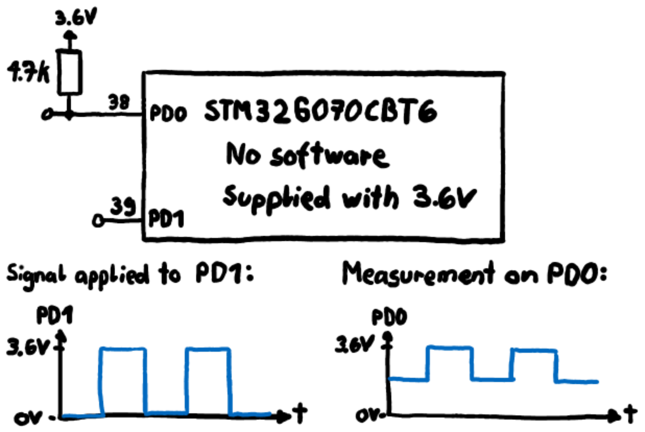
If I apply a square wave of 0V/3.6V to PD1, a similar signal can be observed on PD0. It seems like there is an internal pull-down resistor switching on/off. It does not make a difference whether software configures the pins as inputs, or no software at all is present on the microcontroller.
How can this behavior be explained? Is there an internal mechanism that can cause this? As far as I can tell, these I/O pins should not influence each other at all. Besides using different pins, can anything be done about this using software?

