

Gossamer
Associate III
July 31, 2020
Question

SPI non-DMA max speed ?

  • July 31, 2020
  • 16 replies
  • 6544 views

I am communicating with a TFT LCD and trying to speed things a little bit. At the moment I dont have DMA library written, so I am using standard SPI mode.

I configured the SPI clock as 5Mhz on STM32F407 mcu.

My main clock is PLL on 96Mhz. With APB2 = 2 and APB1 = 4.

Not sure if relevant, but Flash latency is 6 CPU cycles.

Gpio port output speed on CLK,MISO,MOSI is set to Highspeed. (no difference with low speed).

What I am seeing on the logic analyzer is the gaps between each SPI clock. Measuring one byte transmission speed, I am getting average of 300ish Khz instead of 5Mhz.

I only have one interrupt running in the code and that is Systick with 100us tick.
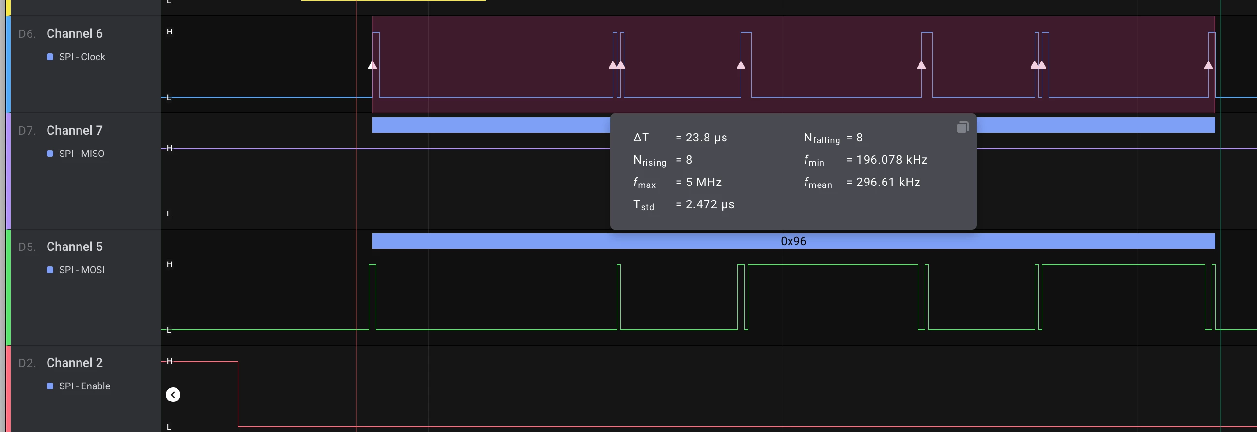
0693W000003BpLnQAK.png

EDIT: One thing was definitely wrong in my setup. CPU WS latency. As my PLL clock is set to 96mhz and mcu works on 3.3v, I had to set 4CPU cycles WS instead of 6 that I originally had. Problem still persists.

This topic has been closed for replies.

16 replies

MM..1
Super User
July 31, 2020

SPI non DMA and DMA have same speed, diff is only offload of mcu when DMA is used.

S.Ma
Principal
July 31, 2020

This forum should force users to specify at least an STM32 family prior to post something related.

There are more than 3 generations of SPI IPs from STM32F103 to STM32H7...

One of them allow 32 bit fifo so it means if you don't use interrupt, you could actually send a burst without clock stretch of your data.

If you run SYSCLK at 96MHz, you could run the SPI at 12 Mhz or higher..

SPI is one of the highest bitrate non differential CMOS level serial interface. It's a true candidate for DMA to offload the core.

Gossamer
GossamerAuthor
Associate III
July 31, 2020

sorry, I added tag for STM32F4.

S.Ma
Principal
July 31, 2020

At SPI 12 MHz, 1 bit period is 8 core clocks. If you send 8 bits one shot, it's 64 clocks.

An interrupt usually takes 20+ cycles. There is no SW involvement when the HW is sending the 8 SCK clock pulses to push a byte in and out...

Gossamer
GossamerAuthor
Associate III
July 31, 2020

So what could cause the clock to chop like its showed in the attached image? I only showed one character (8bits of data). with inconsistent timing between clock cycles. I would expect burst of 8 SCK clock cycles, and then whatever time in between two characters ..

S.Ma
Principal
July 31, 2020

Here is an example of SWD emulation by SPI using non DMA implementation with dynamic SPI bit length adjustments ("3 wire bidir SPI mode")

SYSCLK 48MHz, STM32L4R5

0693W000003BqSuQAK.png

waclawek.jan
Super User
July 31, 2020

> So what could cause the clock to chop like its showed in the attached image?

MM.1 told you above: slow software.

As a test, write a minimal program which only transmits some random data through SPI. Avoid Cube/HAL or any other "library".

JW

Gossamer
GossamerAuthor
Associate III
July 31, 2020

I am not using cube/hal libraries. I am still puzzled on how would any library influence burst of the bits, in my case 8bits on SPI DR register. I could understand delay between 2 bytes of data. This is delay between individual bits of 1 byte of data.

waclawek.jan
Super User
July 31, 2020

> This is delay between individual bits of 1 byte of data.

Ah, sorry then.

So, you program is already a minimal one, which only transmits a single byte and then just loops indefinitely? If not, write such.

Try it with the default (reset) clock settings. If OK, gradually add features of clock. What's the primary clock source?

Is this a "known good" board like Nucleo/Disco? If no, try the same code on one of those.

Try different pins of the same peripheral, and/or a different incarnation of the peripheral.

Read out and check/post the SPI and GPIO registers' content.

JW

Gossamer
GossamerAuthor
Associate III
July 31, 2020

>What's the primary clock source?

I am using external 8Mhz crystal.

>Is this a "known good" board like Nucleo/Disco?

Board is custom made STM32F4 (should be genuine mcu)...

I will try to use SPI2 and see what I get there.

MM..1
Super User
August 1, 2020

I dont write on first post , that your code must be bad, i mean you underrstand.

Use CubeMX and set pins and function as spi . Then in main code use

 HAL_GPIO_WritePin(SPI_CS_GPIO_Port, SPI_CS_Pin, GPIO_PIN_RESET);

 HAL_SPI_Transmit(&hspi2, (uint8_t *)buff, 1, 5);

 SPI_CS_GPIO_Port->BSRR = SPI_CS_Pin;

Nikita91
Lead II
July 31, 2020

How do you get a 5 MHz SPI clock from a 96 MHz sys clock ?

Gossamer
GossamerAuthor
Associate III
July 31, 2020

You are correct. While my code sets demand for 5Mhz clock, I actually set the 6Mhz instead. I got mislead by looking at the logic analyzer output seeing 5Mhz.

S.Ma
Principal
July 31, 2020

Starting debugging with a logic analyser instead of an oscilloscope is a red flag.

If I really want to break the HW shift register from operating, I would simply play with the clock itself, such as peripheral clock/enable/disable on the fly, which is also a red flag.