Jerry Yung
Associate III
August 6, 2019
Solved

About Ouput Compare Insert dead time .

  • August 6, 2019
  • 3 replies
  • 1781 views

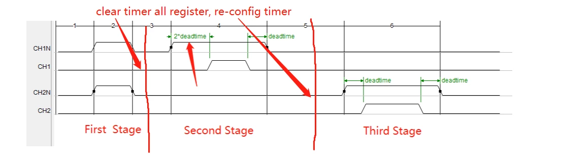
Now , I generate below waveform. Every thing is OK except for red arrow , it indicate a deadtime.but it's longer than other deadtime , in fact , This dead time is twice as large as the other dead time .

divide into three stage :

1�?First Stage , TIM register content

CCMR1.OC2M = 1 ;

CCMR1.OC1M = 1;

CCER.CC1NE = 1;

CCER.CC2NE = 1;

CCER.CC1NP = 1;

CCER.CC2NP = 1;

BDTR.OSSR = 1;

BDTR.MOE = 1;

2�?Second Stage

CCMR1.OC1M = 2;

CCER.CC1E = 1;

CCER.CC1NE = 1;

CCER.CC1NP = 1;

BDTR.OSSR = 1;

BDTR.MOE = 1;

3�?Third Stage

CCMR1.OC2M = 2;

CCER.CC2E = 1;

CCER.CC2NE = 1;

CCER.CC2NP = 1;

BDTR.OSSR = 1;

BDTR.MOE = 1;

when every stage completed , clear all resgister,​ then ,re-config TIM , re-start .

0690X00000986RLQAY.png

so. I don't know why the second stage dead time have problem .​

This topic has been closed for replies.
Best answer by Jerry Yung

config CCER before BDTR ​can be solved

3 replies

waclawek.jan
Super User
August 6, 2019

This again as in your previous post, may be an artefact from the way how you set up things. Hard to tell without seeing the actual code, and also I don't have time to analyze this thoroughly.

Try to single-step through the code clearing/setting the timer registers (while having the timer stopped, maybe through the DBGMCU freeze registers) and observe the impact of each register change on the outputs.

JW

Jerry Yung
Associate III
August 6, 2019

yes , I have solved !

thanks for your help all the time .

Jerry Yung
Jerry YungAuthorBest answer
Associate III
August 7, 2019

config CCER before BDTR ​can be solved