

Rsi
Associate II
April 11, 2019
Question

What is the problem in circuit design with A6986 .
  • April 11, 2019
  • 4 replies
  • 2879 views

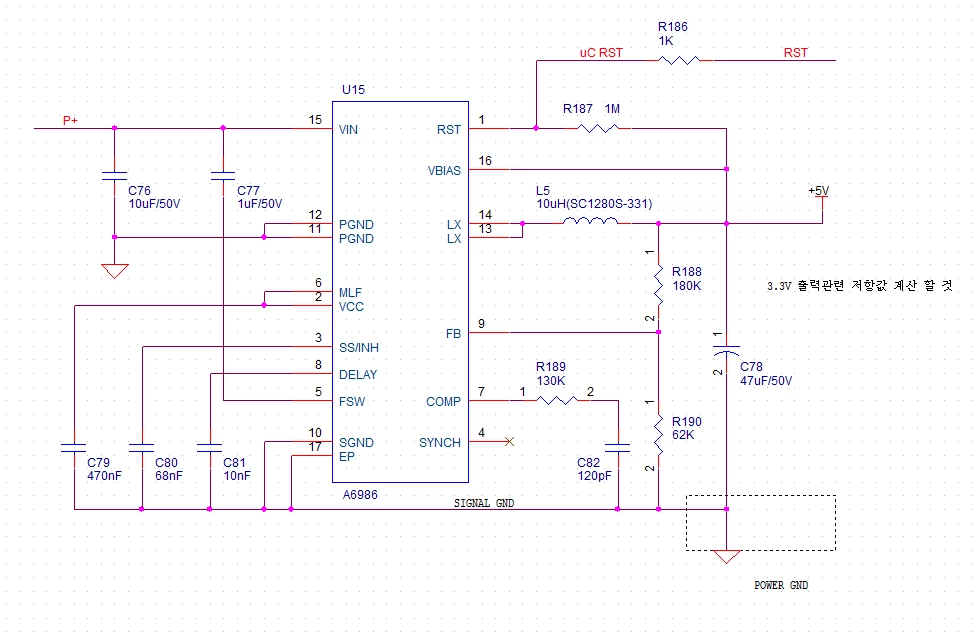
0690X000008AKopQAG.pngHi. I designed the power conversion circuit with A6986.

​

After soldering of this pcb, I powered 24V on power line.

​

And the VIN pin(#15) was damaged.

​

I have no idea what is the problem.

​

when I design the circuit, I consulted the manual, and eval. board circuit.

Please some body help me.

Thank you

​

​

This topic has been closed for replies.

4 replies

MikeDB
Senior II
April 14, 2019

Are your two grounds definitely connected together ?

How do you know it is the VIN pin that is damaged ?

Rsi
RsiAuthor
Associate II
April 14, 2019

Thanks for answering me.

​

The GNDs are definitely connected together.

​

And I saw the VIN pin exploded​ when I powered the 24VDC on power line.

MikeDB
Senior II
April 14, 2019

C78 backwards ?

Rsi
RsiAuthor
Associate II
April 15, 2019

Thanks for answering me.

​

I checked it. But It's on right state.

​

The new uploaded file is another circuit that mine of using a6986, and this circuit

​

has VIN problem too..

​

I've tested a 4.7uF Al. cap. add on the C91, and VIN was not exploded, and output works.

But sadly, I figure out that my L6 component is not good for this circuit, on the simulation, ripple voltage has error.

I just wondering that 4.7uF Al. cap. is right solution on this circuit.

​

​