

Solved
How are signals PHASE_1, 2, and 3 used in the ST-EVAL-ESC01 design?
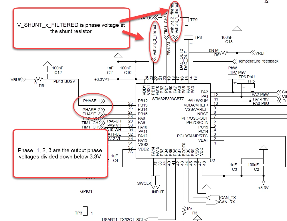
In trying to create a design from scratch using the motor control workbench, I have tried to verify what I see in the ST-EVAL-ESC01 design documentation. In that design (https://www.st.com/en/embedded-software/stsw-esc001v1.html) that there are three phase_x signals, three curr_fdbk x signals, and three vshunt_x_filtered signals. See here:
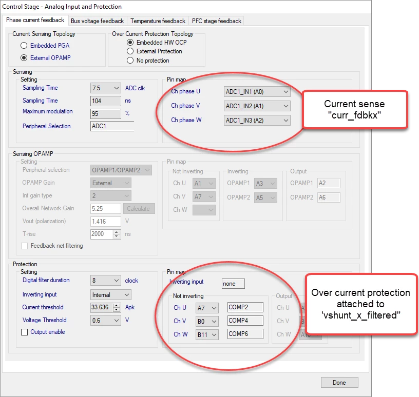
In a startup program using the STM32F303 and Workbench 5.1, it is pretty clear that the current feedback is accounted for (A0/A1/A2) and the over current protection (A7/B9/B11) is for the vshunt_x_filtered signals. Here:
I see nothing in the workbench that accommodates the PHASE_x signals.
What are they used for (if at all) in this design?
Thanks,
Mr. Yan
