parisa
Associate III
January 10, 2017
Question

SPI for reading bits in Half-duplex

  • January 10, 2017
  • 5 replies
  • 921 views
Posted on January 10, 2017 at 10:07

Hi,

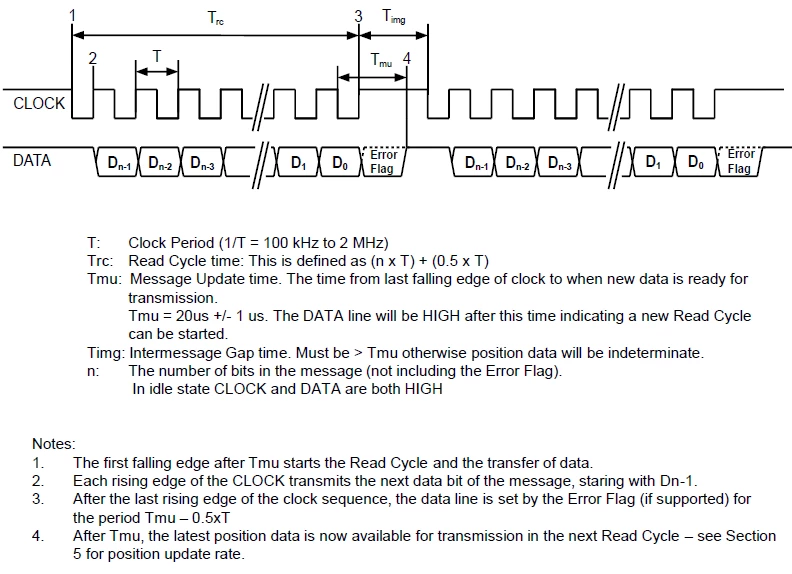
I should read output data from an IC with SPI protocol as shown below.Actually I've got confused how can read each bits with SPI for (n=16 to 32). Or can we another simple approach to read data?

0690X00000605yuQAA.png

I did some settings but I know it is completely wrong to read these bits because most of the time clock is available and not when I need to read.

   SPI_InitStructure.SPI_Direction = SPI_Direction_1Line_Rx;

  SPI_InitStructure.SPI_Mode = SPI_Mode_Master;

  SPI_InitStructure.SPI_DataSize = SPI_DataSize_8b;

   SPI_InitStructure.SPI_CPOL = SPI_CPOL_Low;

  SPI_InitStructure.SPI_CPHA = SPI_CPHA_1Edge;

  SPI_InitStructure.SPI_NSS = SPI_NSS_Soft;

  SPI_InitStructure.SPI_BaudRatePrescaler = SPI_BaudRatePrescaler_64;

  SPI_InitStructure.SPI_FirstBit = SPI_FirstBit_MSB;

  SPI_InitStructure.SPI_CRCPolynomial = 7;

  SPI_Init(SPI3, &SPI_InitStructure);

    This topic has been closed for replies.

    5 replies

    waclawek.jan
    Super User
    January 10, 2017
    Posted on January 10, 2017 at 11:16

    SPI_InitStructure.SPI_Direction = SPI_Direction_1Line_Rx;

    Don't use the halfduplex Rx-Only mode. Use the normal fullduplex mode - you don't need to assign a MOSI pin and it still will work. Then, simply transmit+receive 4 bytes or 2 halfwords.

    JW

    parisa
    parisaAuthor
    Associate III
    January 10, 2017
    Posted on January 10, 2017 at 12:40

    Thanks

    Waclawek.Jan

    for your explanation

    Actually I access only to output data-pin (because the chip sends only data and don't receive anythings) 0690X00000605z4QAA.png

    I changed my normal full-duplex mode and write this program , but I get p[0]=227 or 160 and p[1]=0 always ( in 16bit that is wrong value when the IC change it's value)

    #include <stdio.h>

    #include <string.h>

    #include ''stm32f10x_gpio.h''

    #include ''stm32f10x_rcc.h''

    #include ''stm32f10x_usart.h''

    #include ''stm32f10x_spi.h''

    #define SPI_FLASH SPI3

    #define SPI_CLK RCC_APB1Periph_SPI3

    #define SPI_GPIO GPIOC

    #define SPI_GPIO_CLK RCC_APB2Periph_GPIOC

    #define SPI_PIN_SCK GPIO_Pin_10

    #define SPI_PIN_MISO GPIO_Pin_11

    #define SPI_PIN_MOSI GPIO_Pin_12

    void SPIConfig(void){

    SPI_InitTypeDef SPI_InitStructure;

    GPIO_InitTypeDef GPIO_InitStructure;

    /* Enable SPI and GPIO clocks */

    RCC_APB2PeriphClockCmd( SPI_GPIO_CLK , ENABLE);

    RCC_APB1PeriphClockCmd(RCC_APB1Periph_SPI3,ENABLE);

    GPIO_PinRemapConfig(GPIO_Remap_SPI3, ENABLE);

    /* Configure SPI pins: SCK, MISO and MOSI */

    GPIO_InitStructure.GPIO_Pin = SPI_PIN_SCK | SPI_PIN_MISO | SPI_PIN_MOSI;

    GPIO_InitStructure.GPIO_Mode = GPIO_Mode_AF_PP;

    GPIO_InitStructure.GPIO_Speed = GPIO_Speed_50MHz;

    GPIO_Init(SPI_GPIO, &GPIO_InitStructure);

    SPI_InitStructure.SPI_Direction = SPI_Direction_2Lines_FullDuplex;

    SPI_InitStructure.SPI_Mode = SPI_Mode_Master;

    SPI_InitStructure.SPI_DataSize = SPI_DataSize_8b;

    SPI_InitStructure.SPI_CPOL = SPI_CPOL_Low;

    SPI_InitStructure.SPI_CPHA = SPI_CPHA_1Edge;

    SPI_InitStructure.SPI_NSS = SPI_NSS_Soft;

    SPI_InitStructure.SPI_BaudRatePrescaler = SPI_BaudRatePrescaler_64;

    SPI_InitStructure.SPI_FirstBit = SPI_FirstBit_MSB;

    SPI_InitStructure.SPI_CRCPolynomial = 7;

    SPI_Init(SPI3, &SPI_InitStructure);

    /* Enable the SPI */

    SPI_Cmd(SPI3, ENABLE);

    }

    void delay(){

    int i,j;

    for(i=0;i<10000;i++)

    for(j=0;j<250;j++);

    }

    int main(){

    unsgined char p[3]

    SPIConfig();

    while(1){

    delay();delay();

    while (SPI_I2S_GetFlagStatus(SPI3, SPI_I2S_FLAG_TXE) == RESET);

    SPI_I2S_SendData(SPI3,0xff);

    if(SPI_I2S_GetFlagStatus(SPI3, SPI_I2S_FLAG_RXNE) == SET){

    p[0]=SPI_I2S_ReceiveData(SPI3);}

    while (SPI_I2S_GetFlagStatus(SPI3, SPI_I2S_FLAG_TXE) == RESET);

    SPI_I2S_SendData(SPI3,0xff);

    if(SPI_I2S_GetFlagStatus(SPI3, SPI_I2S_FLAG_RXNE) == SET){

    p[1]=SPI_I2S_ReceiveData(SPI3);

    }

    //print to terminal p[1] and p[0]

    }

    }

    waclawek.jan
    Super User
    January 10, 2017
    Posted on January 10, 2017 at 13:03

    I guess this is the time when you should connect an oscilloscope or a logic analyzer.

    JW

    parisa
    parisaAuthor
    Associate III
    January 10, 2017
    Posted on January 10, 2017 at 20:17

    Thanks waclawek.jan for your suggestion.

    I've seen that my IC works fine when I set SPI data size to 16b.However my main problem is that in this code , I am able to read the first two bytes and when I want to read the next two byte it return again the two first bytes.(it seems that clock stop for a little time (when I want to get p[1] value)and the IC thinks it is a new connection) and I get p[0] is equal to p[1].

    ♯ include <stdio.h>

    ♯ include <string.h>

    ♯ include 'stm32f10x_gpio.h'

    ♯ include 'stm32f10x_rcc.h'

    ♯ include 'stm32f10x_usart.h'

    ♯ include 'stm32f10x_spi.h' ♯ define SPI_FLASH           SPI3

    ♯ define SPI_CLK             RCC_APB1Periph_SPI3

    ♯ define SPI_GPIO                GPIOC

    ♯ define SPI_GPIO_CLK        RCC_APB2Periph_GPIOC

    ♯ define SPI_PIN_SCK         GPIO_Pin_10

    ♯ define SPI_PIN_MISO        GPIO_Pin_11

    ♯ define SPI_PIN_MOSI        GPIO_Pin_12void SPIConfig(void){

    SPI_InitTypeDef  SPI_InitStructure;

      GPIO_InitTypeDef GPIO_InitStructure;  /* Enable SPI and GPIO clocks */

      RCC_APB2PeriphClockCmd( SPI_GPIO_CLK , ENABLE);

    RCC_APB1PeriphClockCmd(RCC_APB1Periph_SPI3,ENABLE);

      GPIO_PinRemapConfig(GPIO_Remap_SPI3, ENABLE);  /* Configure SPI pins: SCK, MISO and MOSI */

      GPIO_InitStructure.GPIO_Pin = SPI_PIN_SCK | SPI_PIN_MISO | SPI_PIN_MOSI;

      GPIO_InitStructure.GPIO_Mode = GPIO_Mode_AF_PP;

      GPIO_InitStructure.GPIO_Speed = GPIO_Speed_50MHz;

      GPIO_Init(SPI_GPIO, &GPIO_InitStructure);


        SPI_InitStructure.SPI_Direction = SPI_Direction_2Lines_FullDuplex;

      SPI_InitStructure.SPI_Mode = SPI_Mode_Master;

      SPI_InitStructure.SPI_DataSize = SPI_DataSize_16b;

     SPI_InitStructure.SPI_CPOL = SPI_CPOL_Low;

      SPI_InitStructure.SPI_CPHA = SPI_CPHA_1Edge;

      SPI_InitStructure.SPI_NSS = SPI_NSS_Soft;

      SPI_InitStructure.SPI_BaudRatePrescaler = SPI_BaudRatePrescaler_64;

      SPI_InitStructure.SPI_FirstBit = SPI_FirstBit_MSB;

      SPI_InitStructure.SPI_CRCPolynomial = 7;

      SPI_Init(SPI3, &SPI_InitStructure);  /* Enable the SPI  */

      SPI_Cmd(SPI3, ENABLE);

    }


    void delay(){

        int i,j;

        for(i=0;i<10000;i++)

        for(j=0;j<250;j++);

    }int main(){    

    unsgined char p[3]    

    SPIConfig();            


        while(1){            

        delay();delay();    while (SPI_I2S_GetFlagStatus(SPI3, SPI_I2S_FLAG_TXE) == RESET);

        SPI_I2S_SendData(SPI3,0xffff);

        if(SPI_I2S_GetFlagStatus(SPI3, SPI_I2S_FLAG_RXNE) == SET){

        p[0]=SPI_I2S_ReceiveData(SPI3);}    while (SPI_I2S_GetFlagStatus(SPI3, SPI_I2S_FLAG_TXE) == RESET);    

        SPI_I2S_SendData(SPI3,0xff);    

        if(SPI_I2S_GetFlagStatus(SPI3, SPI_I2S_FLAG_RXNE) == SET){

        p[1]=SPI_I2S_ReceiveData(SPI3);    }


    //print to terminal p[1] and p[0]


        }


    }

    How can solve this states?