

PWM glitch problem??
Posted on July 24, 2011 at 17:03
Has now been running myself crazy here today when I took on the next problem.
Have long known that there are small errors in the PWM signal that is off.
And after my solution that I post earlier, this has been more than before, probably anyway.
The thing is that I update the PWM duty cycle each ms, and sometimes it does not seem that the PWM signal is working after the update.
the PWM signal is lost untill the next update.
the error is not regular, it come and go.
I have been looking for how to update the PWM channels on the STM32 MCU, which I'm working towards.
Have seen this problem before on other designs that I've driven Buzzers via PWM, then I solved it by not updating as often to minimize the problem.
But this is not a solution in this case.
I have another card that I have tested the same code on and it is the same error there, so it's not wrong on the chip if it is not a bug.
I've looked directly at the output pin of the STM32 and the same error there.
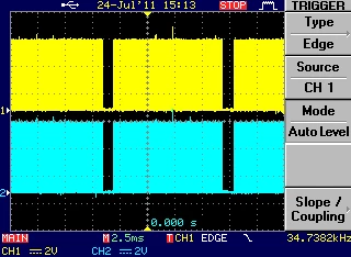
Here can you seen that the signal is quiet in for a millisecond
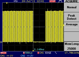
it is updating the PWM channels with the same value every time
duty = 50%
Someone that knows how to update the PWM timer in the best way?
update code
void SetMotorPWM(signed int MotorA, signed int MotorB)
{
TIM_OCInitTypeDef TIM_OCInitStructure;
// Normalize values
if(MotorA < -2000)
{ MotorA = -2000; }
else if(MotorA > 2000)
{ MotorA = 2000; }
if(MotorB < -2000)
{MotorB = -2000; }
else if(MotorB > 2000)
{MotorB = 2000;}
/* PWM1 Mode configuration: Motor Channel A */
TIM_OCInitStructure.TIM_OCMode = TIM_OCMode_PWM1;
TIM_OCInitStructure.TIM_Pulse = (unsigned int)(MotorA + 2000);
TIM_OC2Init(TIM2, &TIM_OCInitStructure);
/* PWM1 Mode configuration: Motor Channel B */
TIM_OCInitStructure.TIM_OCMode = TIM_OCMode_PWM1;
TIM_OCInitStructure.TIM_Pulse = (unsigned int)(MotorB + 2000);
TIM_OC3Init(TIM2, &TIM_OCInitStructure);
}
Init code that I use for TIM2 and channel 2 & 3
void MotorPWMInit(void)
{
TIM_TimeBaseInitTypeDef TIM_TimeBaseStructure;
TIM_OCInitTypeDef TIM_OCInitStructure;
GPIO_InitTypeDef GPIO_InitStructure;
unsigned int PrescalerValue;
// Configure the Motor A PWM output pin
RCC_APB2PeriphClockCmd(RCC_APB2Periph_GPIO_PWM_A, ENABLE);
GPIO_InitStructure.GPIO_Mode = GPIO_Mode_AF_PP;
GPIO_InitStructure.GPIO_Pin = PWM_A_PIN;
GPIO_InitStructure.GPIO_Speed = GPIO_Speed_50MHz;
GPIO_Init(PWM_A_PORT, &GPIO_InitStructure);
// Configure the Motor B PWM output pin
RCC_APB2PeriphClockCmd(RCC_APB2Periph_GPIO_PWM_B, ENABLE);
GPIO_InitStructure.GPIO_Mode = GPIO_Mode_AF_PP;
GPIO_InitStructure.GPIO_Pin = PWM_B_PIN;
GPIO_InitStructure.GPIO_Speed = GPIO_Speed_50MHz;
GPIO_Init(PWM_B_PORT, &GPIO_InitStructure);
// Timer clock
RCC_APB2PeriphClockCmd(RCC_APB2Periph_GPIOA |RCC_APB2Periph_AFIO, ENABLE);
RCC_APB1PeriphClockCmd(RCC_APB1Periph_TIM2, ENABLE);
/* Time Base configuration */
TIM_TimeBaseStructure.TIM_Period = 4000;
TIM_TimeBaseStructure.TIM_Prescaler = 0;
TIM_TimeBaseStructure.TIM_ClockDivision = 0;
TIM_TimeBaseStructure.TIM_CounterMode = TIM_CounterMode_Up;
TIM_TimeBaseInit(TIM2, &TIM_TimeBaseStructure);
/* PWM1 Mode configuration: Channel1 */
TIM_OCInitStructure.TIM_OCMode = TIM_OCMode_PWM1;
TIM_OCInitStructure.TIM_OutputState = TIM_OutputState_Enable;
TIM_OCInitStructure.TIM_Pulse = 2000;
TIM_OCInitStructure.TIM_OCPolarity = TIM_OCPolarity_High;
TIM_OCInitStructure.TIM_OCIdleState = TIM_OCIdleState_Set;
TIM_OCInitStructure.TIM_OCNIdleState = TIM_OCIdleState_Reset;
// Motor A channel
TIM_OC2Init(TIM2, &TIM_OCInitStructure);
TIM_OC2PreloadConfig(TIM2, TIM_OCPreload_Enable);
// Motor B channel
TIM_OC3Init(TIM2, &TIM_OCInitStructure);
TIM_OC3PreloadConfig(TIM2, TIM_OCPreload_Enable);
TIM_ARRPreloadConfig(TIM2, ENABLE);
/* TIM1 enable counter */
TIM_Cmd(TIM2, ENABLE);
/* TIM1 Main Output Enable */
TIM_CtrlPWMOutputs(TIM2, ENABLE);
}
