

Mehmood Nurmohamed
Associate
October 11, 2017
Solved

STM32F767ZI Timer Interrupt

  • October 11, 2017
  • 9 replies
  • 2478 views
Posted on October 11, 2017 at 23:35

Hello,

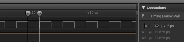
I am having some difficulties wrapping my head around what's happening with my TIM3 interrupt.  I am creating a timer class for my application.  It needs a 1 microsecond resolution.  For some reason I can only achieve a 2 microsecond resolution.  I started with the STM32F7Cube TIM_Base example for this Nucleo board.  The system core clock is 216MHz.  I have hopefully followed the instructions for configuring the timer using the method from the MCU documentation:

Update_event = TIM_CLK/((PSC + 1)*(ARR + 1)*(RCR + 1))  

My code is as follows:

// Initialize TIMx peripheral as follows for a 1us tick (1MHz):

// + Period = SystemCoreClock/1000000 - 1

// + ClockDivision = 0

// + Counter direction = Up

TimHandle.Init.Period = (SystemCoreClock/TICK_RATE_HZ) - 1; // TICK_RATE_HZ = 1x10^6

TimHandle.Init.Prescaler = 0;

TimHandle.Init.ClockDivision = TIM_CLOCKDIVISION_DIV1;

TimHandle.Init.CounterMode = TIM_COUNTERMODE_UP;

TimHandle.Init.RepetitionCounter = 0;

TimHandle.Init.AutoReloadPreload = TIM_AUTORELOAD_PRELOAD_DISABLE;

if (HAL_TIM_Base_Init(&TimHandle) != HAL_OK)

{

/* Initialization Error */

Error_Handler();

}

//##-2- Start the TIM Base generation in interrupt mode ####################

if (HAL_TIM_Base_Start_IT(&TimHandle) != HAL_OK)

{

/* Starting Error */

Error_Handler();

}
0690X00000608aLQAQ.png

Many thanks in advance!

    This topic has been closed for replies.
    Best answer by Tesla DeLorean
    Posted on October 17, 2017 at 21:13

    If the clock runs at 108 MHz then the period needs to be 107 ie 108-1 to get to 1us (or 1 MHz)

    Interrupting at MHz rates is not recommended, it will burn a ridiculous number of cycles, more so with HAL.

    If you want clock signals, use the TIM to generate the signal in HW, not with interrupts.

    1 MHz 0.5us width, Prescaler = 0, Period = 107, Pulse = 54 (50/50 Duty), PWM Mode

    500 KHz 1us width, Prescaler = 0, Period = 215, Pulse = 108 (50/50 Duty), PWM Mode

    9 replies

    S.Ma
    Principal
    October 13, 2017
    Posted on October 13, 2017 at 04:36

    On a general note, check the top level clock tree feeding the timer block diagram to see if there is a div2 prescaler not shown at the timer block diagram level.

    Joerg Wagner
    Senior III
    October 15, 2017
    Posted on October 15, 2017 at 13:25

    Like KIC8462852 EPIC2024278916 wrote, check the clock source.

    But you measured 50% only of the period. So in your case it is 1/4 of the desired frequency

    and not a div2 prescaler.

    - Joerg -

    Mehmood Nurmohamed
    Associate
    October 16, 2017
    Posted on October 16, 2017 at 19:58

    0690X00000608NhQAI.png

    Hello,

    Thank you both for the analysis.  I took the existing example for TIM3 from the STM32CubeF7 example project and verified the clock source for TIM3.  In this case TIM3CLK = PCLK1*2 where PCLK1=HCLK/4.  Using that information TIM3CLK = HCLK/2 = SystemCoreClock/2.  For this target the SystemCoreClock is 216 MHz.  As a result TIM3CLK is 108 MHz.

    Is there something I'm missing?  I've played with all sorts of permutations of the Prescaler and Period but can't seem to achieve the 1us period I need.  I even found a clock calculator from Mikroelectronica.  Their ARR and PSC values correspond with what I calculated (PSC = 0, ARR = 215) but I still don't have the right 1 us clock rate desired.

    Many thanks for any other tips.

    Joerg Wagner
    Senior III
    October 17, 2017
    Posted on October 17, 2017 at 15:51

    To reproduce I wrote a simple app with Timer 3 using your values.

    This is my init code created with CubeMX:

    /* TIM3 init function */

    static void MX_TIM3_Init(void)

    {

    TIM_ClockConfigTypeDef sClockSourceConfig;

    TIM_MasterConfigTypeDef sMasterConfig;

    htim3.Instance = TIM3;

    htim3.Init.Prescaler = 0;

    htim3.Init.CounterMode = TIM_COUNTERMODE_UP;

    htim3.Init.Period = 216;

    htim3.Init.ClockDivision = TIM_CLOCKDIVISION_DIV1;

    htim3.Init.AutoReloadPreload = TIM_AUTORELOAD_PRELOAD_DISABLE;

    if (HAL_TIM_Base_Init(&htim3) != HAL_OK)

    {

    _Error_Handler(__FILE__, __LINE__);

    }

    sClockSourceConfig.ClockSource = TIM_CLOCKSOURCE_INTERNAL;

    if (HAL_TIM_ConfigClockSource(&htim3, &sClockSourceConfig) != HAL_OK)

    {

    _Error_Handler(__FILE__, __LINE__);

    }

    sMasterConfig.MasterOutputTrigger = TIM_TRGO_RESET;

    sMasterConfig.MasterSlaveMode = TIM_MASTERSLAVEMODE_DISABLE;

    if (HAL_TIMEx_MasterConfigSynchronization(&htim3, &sMasterConfig) != HAL_OK)

    {

    _Error_Handler(__FILE__, __LINE__);

    }

    }

    To test the frequency:

    void HAL_TIM_PeriodElapsedCallback(TIM_HandleTypeDef *htim)

    {

    if (htim->Instance == TIM3) {

    HAL_GPIO_TogglePin(dbgpin_GPIO_Port, dbgpin_Pin);

    }

    }

    The results are in the attached PDF. Almost perfect.

    What are you looking for?

    ________________

    Attachments :

    document.pdf : https://st--c.eu10.content.force.com/sfc/dist/version/download/?oid=00Db0000000YtG6&ids=0680X000006HyN0&d=%2Fa%2F0X0000000b6h%2FBb9RnZkSZliJLwuQCN6g9JoAnS9024K.aJpnbTzht8Y&asPdf=false
    Mehmood Nurmohamed
    Associate
    October 17, 2017
    Posted on October 17, 2017 at 19:02

    Hi Joerg,

    Thank you for providing the report.  I too was able to get a 2us pulse width, originally.  My desire is to get a 1us resolution (ie pulse width).  If this is not possible then is there an explanation for that?  The best I can seem to do is this:

    0690X00000608c3QAA.png

    Many thanks for taking the time for your above analysis.

    Tesla DeLorean
    Tesla DeLoreanBest answer
    Guru
    October 17, 2017
    Posted on October 17, 2017 at 21:13

    If the clock runs at 108 MHz then the period needs to be 107 ie 108-1 to get to 1us (or 1 MHz)

    Interrupting at MHz rates is not recommended, it will burn a ridiculous number of cycles, more so with HAL.

    If you want clock signals, use the TIM to generate the signal in HW, not with interrupts.

    1 MHz 0.5us width, Prescaler = 0, Period = 107, Pulse = 54 (50/50 Duty), PWM Mode

    500 KHz 1us width, Prescaler = 0, Period = 215, Pulse = 108 (50/50 Duty), PWM Mode

    Tips, Buy me a coffee, or three.. PayPal Venmo (See Profile) Up vote any posts that you find helpful, it shows what's working..
