Solved
what's wrong with my ADC DMA initialization?
Posted on November 15, 2017 at 22:13
Hello,
I'm trying to trigger an ADC conversion externally from TRGO2 and store it to a buffer through DMA. However, it doesn't appear that anything is being written to that buffer. Could someone please look through my initialization code and let me know if I'm messing something up during the initialization?
void InitADC(void)
{
int i;
ADC_InitTypeDef ADC_InitStructure;
ADC_CommonInitTypeDef ADC_CommonInitStructure;
GPIO_InitTypeDef GPIO_InitStructure;
NVIC_InitTypeDef NVIC_InitStructure;
DMA_InitTypeDef DMA_InitStructure;

RCC_AHBPeriphClockCmd(RCC_AHBPeriph_DMA1, ENABLE);
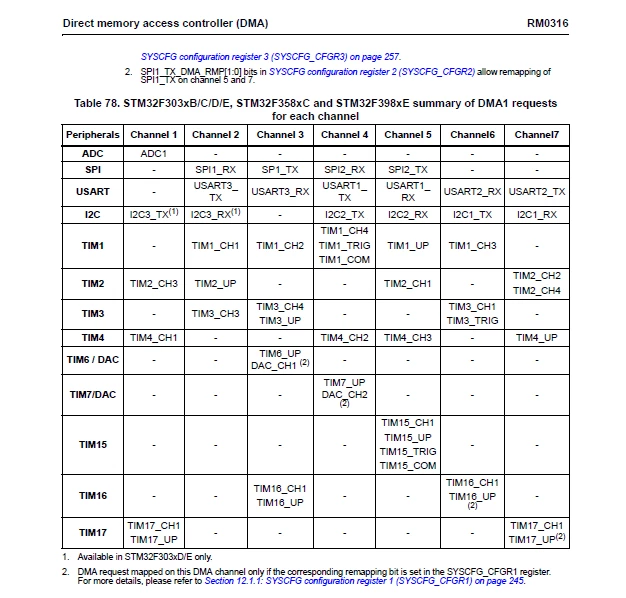
DMA_DeInit(DMA1_Channel1);
DMA_InitStructure.DMA_BufferSize = 2;
DMA_InitStructure.DMA_DIR = DMA_DIR_PeripheralSRC;
DMA_InitStructure.DMA_M2M = DMA_M2M_Disable;
DMA_InitStructure.DMA_MemoryBaseAddr = (uint32_t)adcBuffer;
DMA_InitStructure.DMA_MemoryDataSize = DMA_MemoryDataSize_HalfWord;
DMA_InitStructure.DMA_MemoryInc = DMA_MemoryInc_Enable;
DMA_InitStructure.DMA_Mode = DMA_Mode_Circular;
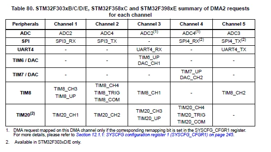
DMA_InitStructure.DMA_PeripheralBaseAddr = (uint32_t)&ADC2->DR;
DMA_InitStructure.DMA_PeripheralDataSize = DMA_PeripheralDataSize_HalfWord;
DMA_InitStructure.DMA_PeripheralInc = DMA_PeripheralInc_Disable;
DMA_InitStructure.DMA_Priority = DMA_Priority_High;
DMA_Init(DMA1_Channel1, &DMA_InitStructure);
DMA_Cmd(DMA1_Channel1, ENABLE);
/* Configure the ADC clock */
RCC_ADCCLKConfig(RCC_ADC12PLLCLK_Div2);
/* Enable ADC12 clock */
RCC_AHBPeriphClockCmd(RCC_AHBPeriph_ADC12, ENABLE);
ADC_CommonInitStructure.ADC_Mode = ADC_Mode_Independent;
ADC_CommonInitStructure.ADC_Clock = ADC_Clock_SynClkModeDiv1;
ADC_CommonInitStructure.ADC_DMAAccessMode = ADC_DMAAccessMode_1;
ADC_CommonInitStructure.ADC_DMAMode = ADC_DMAMode_OneShot;
ADC_CommonInitStructure.ADC_TwoSamplingDelay = 0;
ADC_CommonInit(ADC2, &ADC_CommonInitStructure);
/* GPIOA Periph clock enable */
RCC_AHBPeriphClockCmd(RCC_AHBPeriph_GPIOA, ENABLE);
/* Configure ADC2 Channel1 as analog input */
GPIO_InitStructure.GPIO_Pin = GPIO_Pin_4 | GPIO_Pin_5;
GPIO_InitStructure.GPIO_Mode = GPIO_Mode_AN;
GPIO_InitStructure.GPIO_PuPd = GPIO_PuPd_NOPULL ;
GPIO_Init(GPIOA, &GPIO_InitStructure);
ADC_StructInit(&ADC_InitStructure);
/* Calibration procedure */
ADC_VoltageRegulatorCmd(ADC2, ENABLE);
for(i = 0; i < 1000; i++) {}
ADC_SelectCalibrationMode(ADC2, ADC_CalibrationMode_Single);
ADC_StartCalibration(ADC2);
while(ADC_GetCalibrationStatus(ADC2) != RESET );
ADC_InitStructure.ADC_ContinuousConvMode = ADC_ContinuousConvMode_Disable;
ADC_InitStructure.ADC_Resolution = ADC_Resolution_12b;
ADC_InitStructure.ADC_ExternalTrigConvEvent = ADC_ExternalTrigConvEvent_10;
ADC_InitStructure.ADC_ExternalTrigEventEdge = ADC_ExternalTrigEventEdge_RisingEdge;
ADC_InitStructure.ADC_DataAlign = ADC_DataAlign_Right;
ADC_InitStructure.ADC_OverrunMode = ADC_OverrunMode_Disable;
ADC_InitStructure.ADC_AutoInjMode = ADC_AutoInjec_Disable;
ADC_InitStructure.ADC_NbrOfRegChannel = 2;
ADC_Init(ADC2, &ADC_InitStructure);
/* ADC2 regular channel1 configuration */
ADC_RegularChannelConfig(ADC2, ADC_Channel_1, 1, ADC_SampleTime_7Cycles5);
ADC_RegularChannelConfig(ADC2, ADC_Channel_2, 2, ADC_SampleTime_7Cycles5);
#warning 'Figure out priority'
/* Configure and enable ADC2 interrupt */
NVIC_InitStructure.NVIC_IRQChannel = ADC1_2_IRQn;
NVIC_InitStructure.NVIC_IRQChannelSubPriority = 0;
NVIC_InitStructure.NVIC_IRQChannelPreemptionPriority = 0;
NVIC_InitStructure.NVIC_IRQChannelCmd = ENABLE;
NVIC_Init(&NVIC_InitStructure);
/* Enable EOS interrupt */
ADC_ITConfig(ADC2, ADC_IT_EOS, ENABLE);
/* Enable ADC2 */
ADC_Cmd(ADC2, ENABLE);
ADC_DMACmd(ADC2, ENABLE);
/* wait for ADRDY */
while(!ADC_GetFlagStatus(ADC2, ADC_FLAG_RDY));
/* Start ADC2 Software Conversion */
ADC_StartConversion(ADC2);
}
void ADC1_2_IRQHandler(void)
{
 if(ADC_GetFlagStatus(ADC2, ADC_FLAG_EOS) != RESET)
 {
 /* Clear ADC2 AWD pending interrupt bit */
 ADC_ClearITPendingBit(ADC2, ADC_IT_EOS);
adcBuffer[0] = (adcBuffer[0] * ADC_VREF) >> 12;
adcBuffer[1] = (adcBuffer[1] * ADC_VREF) >> 12;
 }
}�?�?�?�?�?�?�?�?�?�?�?�?�?�?�?�?�?�?�?�?�?�?�?�?�?�?�?�?�?�?�?�?�?�?�?�?�?�?�?�?�?�?�?�?�?�?�?�?�?�?�?�?�?�?�?�?�?�?�?�?�?�?�?�?�?�?�?�?�?�?�?�?�?�?�?�?�?�?�?�?�?�?�?�?�?�?�?�?�?�?�?�?�?�?�?�?�?�?�?�?�?�?�?�?�?�?�?�?�?�?
Question 2: The schematic I'm working with is using ADC peripheral 1 and ADC peripheral 2 as part of the group of signals I'd like to sample during the TRGO2 event. Do I need to set up a different DMA channel to capture the sample from the other peripheral?
Thanks.
#dma-adc #dma-transfer #stm32f3