Associate
October 20, 2026
Question

Viper265 Input higher than 420VAC


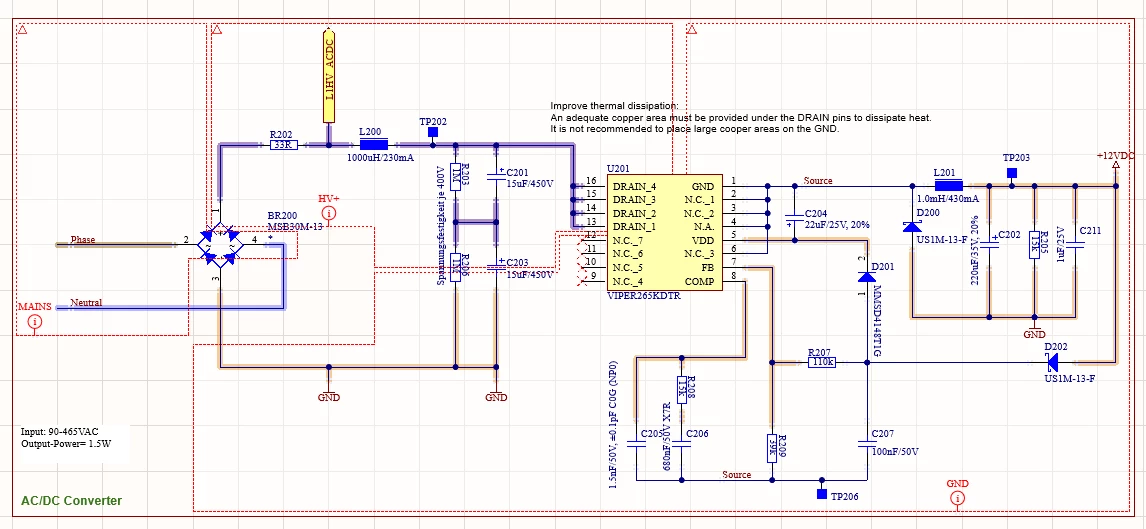
I have a problem with the Viper265K. I copied the basic circuit from the eval board (STEVAL-VP26K01B).

The desired input voltage range is 90-465VAC 50/60Hz
Output voltage 12V
Output current ~0.1A

Currently, I have a resistive load connected to verify the power supply. Unfortunately, the output voltage collapses at higher input voltages >420VAC or it just switches on/off very briefly.

The coil L201 is a 7447714102 with I: 0.43A / Isat: 0.55A
When I replace L201 with the inductor from the eval board, the maximum input voltage is still not higher.

But the eval board works perfectly with 12V and the maximum input voltage as declared by ST.

What am I doing wrong?
 

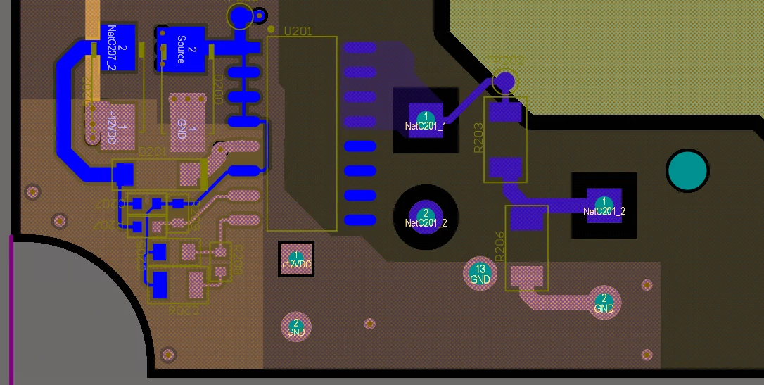
Bottom Layout


7 replies

Associate
October 20, 2026

Hi,

Could you share a full schematic and board layout please if acceptable?

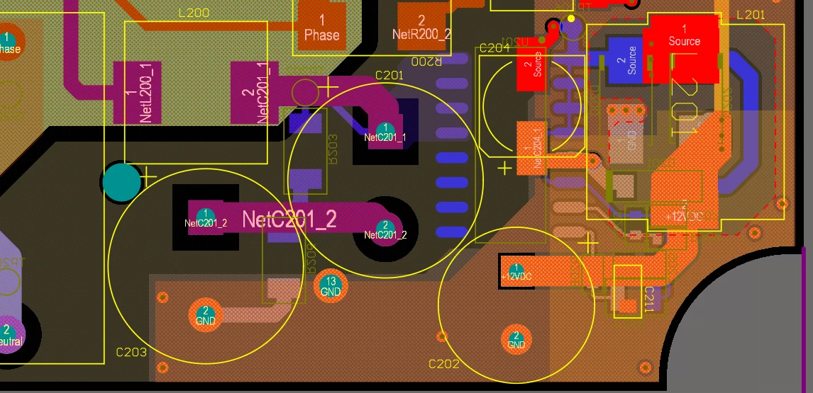
I would be inclined to believe the problem, or at least a problem, is that D200 is placed directly underneath the power inductor (L201) while its high voltage switching traces run very near to your feedback lines, this can create severe capacitive and magnetic coupling. At high input voltages arrangement may act like an miniature antenna, injecting electrical noise spikes directly into the Viper's feedback pin and tricking the controller into constantly shutting down to protect itself.


Is this a 2 or 4 layer board? Looks like 2 to me.


Philipp_KAuthor
Associate
October 20, 2026

Hi, 

Yes, the D200 is just below the L201. It's a 4-layer PCB.

I also added some extra pictures for a better understanding of the layer structure.


TOP, plane GND

Midlayer 1  ; plane 12V


Midlayer 2 ; plane GND


Bottom ; plane GND

Associate
October 20, 2026

what is each midlayer doing?

My assumption from the photos is layer 2 is 12v and layer 3 is gnd. (Thanks for the edit. I can see it now)

Associate
October 20, 2026


Looking at your layout and 4 layer stackup, I think your issue is likely high-voltage noise coupling into the feedback loop.


The cathode/switching node of D200 experiences massive 600V+ voltage swings at 60 kHz. Because the diode is stacked directly underneath the L201 inductor, its high-voltage switching traces are capacitively coupling these sharp transients straight through the inner board layers and into the adjacent feedback lines. Effectively its acting like a capacitor or more accurately a parasitic capacitor .This contaminates your feedback reference, tricking the Viper into a continuous protection shutdown.


If you can spare a board to test this theory:


Use a stanley knife to carefully cut the trace to D200 on the board, and temporarily solder D200 using small wires completely away from the inductor and feedback lines. If the circuit suddenly works at 465VAC, your layout coupling is the culprit.


Philipp_KAuthor
Associate
October 20, 2026

Hi,

I don't have access to the lab today, but I will test this with the D200 tomorrow.

Thanks already for the hint.


Regards Philipp

Philipp_KAuthor
Associate
October 21, 2026

Hi,

Today we desoldered the D200 and tested it a bit offset with 15mm and 60mm connection wires. Unfortunately, it didn’t help at all; we could NOT increase the maximum input voltage.  

We also tried measuring the pulse time, but we’re already at 380ns, which is below the minimum on-time from 480ns. unfortunately, I can’t successfully reproduce this in eDesignSuite either. Also, the Evalboard can’t be simulated in eDesignSuite. There are also errors due to too short ON time.


Associate
October 21, 2026

I feel silly for not spotting this issue sooner! I would change your 1.0mH inductor to a 2.2 mH inductor. This means it will ramp current more than twice as slow as the original inductor, stretching the pulse time safely past minimum on time requirement.


If this does not work then I am at a loss. Though I would move your diode position in future boards as mounting switching components directly under inductors is always bad news.