

VIPER16LDTR Buck Converter — COMP stuck at 0.75V, very low duty cycle, output 500mV despite correct 60kHz switching1
Hello ST Community,
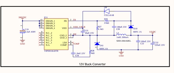
We are using the VIPER16LDTR in a non-isolated buck converter to generate 12VDC from a 325VDC rectified bus. The input is 230VAC from a Variac, rectified to approximately 325VDC through our input rectification stage. The circuit follows the standard buck topology from VIPER16 datasheet Figure 17. Operating conditions: Vin = 325VDC, Vout = 12V, Iout = approximately 250mA, fsw = 60kHz (VIPER16L type confirmed with differential probe).
What we have verified as healthy:
- DRAIN pins 13-16: 325VDC present and confirmed
- VDD pin 5 (via C21, 10uF): 12V present — internal HV startup source working
- SW node pin 2: 60kHz switching waveform confirmed with differential oscilloscope probe
- D9 (FDLL4148): forward drop confirmed, correct orientation
- D10, D11 (600V/1A): both healthy in diode mode
- L3 (1mH, SRR1206102KL): DCR = 0.25Ω, solder joints inspected and reflowed, continuity confirmed
- C22 (220uF, 25V output cap): 1.4MΩ to GND — no leakage, no short
- 12V rail to GND (load side): 4.5kΩ — no downstream short
- FB divider (R26/R27): reading 500mV correctly reflecting actual output via divider ratio
The problem:
Despite the IC switching correctly at 60kHz and VDD being present at 12V, we are observing the following faults together:
- COMP pin (pin 8) is permanently stuck at 0.75V — well below the VCOMPL burst mode threshold of 1.1V typical per datasheet Table 8
- Duty cycle is very low — the ON pulse on the SW node is extremely narrow, much less than the expected ~3.7% (12V/325V). The IC appears to be firing only brief occasional pulses rather than sustained PWM
- Output (C22) is stuck at 500mV and never builds up to 12V
The IC is not in a fault latch or thermal shutdown — it is actively producing switching pulses at 60kHz on every power cycle. The output simply never rises despite switching being present.
We believe the very low duty cycle and the COMP being stuck at 0.75V are related — with COMP below VCOMPL the IC enters burst mode per the datasheet, which suppresses duty cycle to near zero and starves the output. However we cannot determine what is causing COMP to be stuck below the burst mode threshold in the first place, since all external components have been verified and replaced.
What we have tried:
- Replaced IC4 (VIPER16LDTR) twice with new parts — identical symptoms on every replacement
- Replaced all surrounding passive components (R26, R27, R28, C20, C21, C22, C23, C24, D9, D10, D11, L3) — identical symptoms persist
- Inspected and reflowed all solder joints — no change
- Confirmed no short on output or load side
- Confirmed switching frequency with differential oscilloscope probe — 60kHz present on SW node
Additional observation:
We have two boards built from the identical schematic and BOM. One board works correctly and produces 12V with normal duty cycle. The other board shows the above fault — very low duty cycle, COMP at 0.75V, output at 500mV. Both boards have been measured and all component values are within tolerance. We cannot explain why two identical boards built from the same components and schematic behave differently.
Our compensation network values:
- R28 (Rc) = 1kΩ
- C24 (Cc) = 1.8nF
- No Cp fitted
Questions for ST:
- With COMP stuck at 0.75V (below VCOMPL = 1.1V typical), very low duty cycle, and the IC confirmed switching at 60kHz with VDD present at 12V — what is the most likely root cause and what should we check next?
- Is there any internal IC condition — for example a protection latch, OTP event, or internal state — that could hold COMP below VCOMPL independently of the external compensation network, and that could persist across power cycles?
- Could the LIM pin (pin 6) being left floating cause any startup or COMP behavior issue in a buck topology? Our load is 250mA which is well below the default IDlim of 0.4A.
- Are our compensation network values (R28 = 1kΩ, C24 = 1.8nF) suitable for this operating point (Vin = 325VDC, Vout = 12V, Iout = 250mA, fsw = 60kHz)? Could wrong compensation values cause COMP to be permanently suppressed below the burst mode threshold, resulting in very low duty cycle and output stuck at 500mV?
- Is it possible for the IC to switch at 60kHz on the SW node while simultaneously being in burst mode — or does burst mode completely stop all switching? We are seeing 60kHz on the scope but the duty cycle appears very low, which is causing some confusion in our diagnosis.
We are stuck on this issue and would greatly appreciate ST's guidance on what to investigate next. Any help is much appreciated.