Associate
June 19, 2026
Question

STPM32 Reset in Operation with no external factors

  • June 19, 2026
  • 1 reply
  • 22 views

Following this issue, and the advice from ​@Didier HERROUIN, we have implemented the SYN and SCS initialisation,(see schematic) , and are still finding that our STPM32 chips are resetting their UART config during operation.

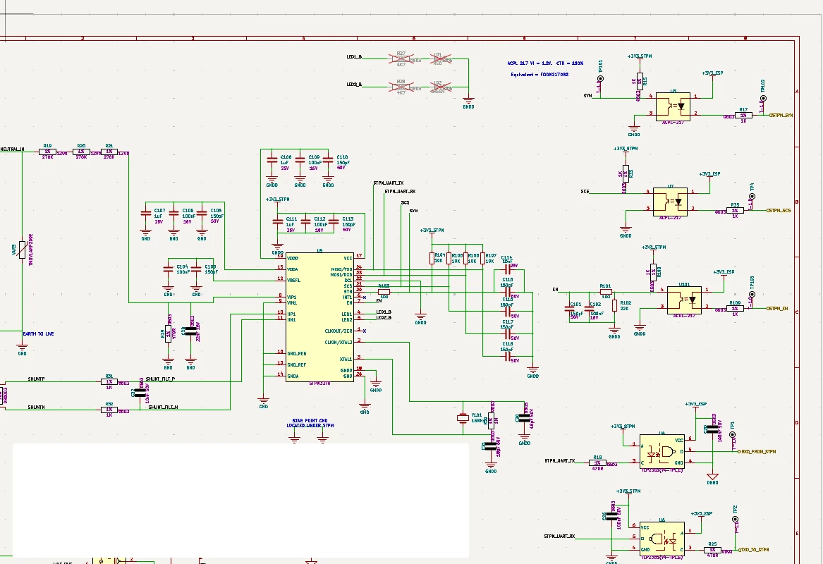
For context, the firmware first pulses SYN 3 times, then SCK, and configures the STPM32 UART to 115200 baud. This runs fine for a few minutes, and then we detect a failure because the chip resets to 9600 baud for no reason, leading to a timeout on the microcontroller.

The voltage supply to this device is perfectly stable at 3.3V.

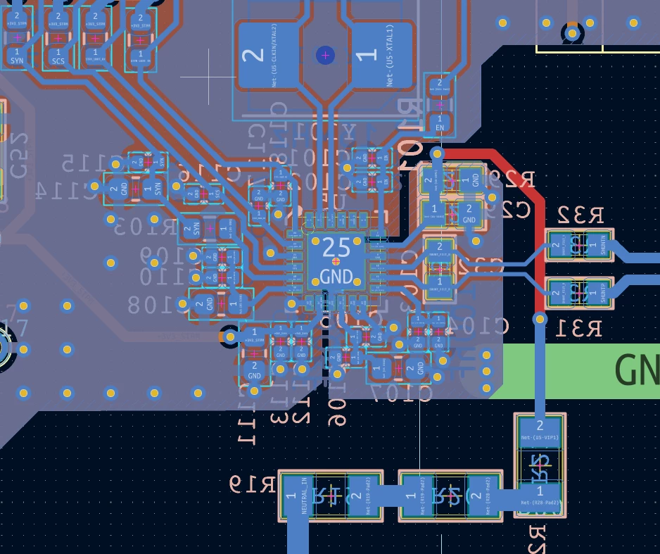
We have followed all advice regarding isolation and ground planes, as you can see in the attached PCB design.

I desperately require assistance with this problem. My only solution now is to re-configure the STPM32 every time it resets, but this will definitely lead to inaccuracies as some energy measurements will be lost during configuration and timeout detection. 

The only common thread I can piece together is a hint from one Mark Germagian, who claims to have only found this on chips with a 2025 date code.

I am experiencing this on chips with the marking “CHN313”, but did not see this on chips marked “CHN331”, which leads me to believe this is a manufacturing defect.


1 reply

Didier HERROUIN
ST Technical Moderator
June 22, 2026

Dear Dane Slattery,

There are several way to reset the UART configuration (I assume that all the registers are also reset) on purpose :

  • By a SW reset (register DSP_CR3), but I assume that you did not implement this 
  • By using SYN signals : 3 SYN pulses will generate a reset of all registers.
    Please probe this signal to ensure no spurious can be seen.
  • By EN signal : it seems correctly connected in you schematics.
    Nevertheless, please probe this signal to ensure no spurious can be seen.

I have noticed in your schematics that the shunt seems not connected to GND.
One side of the shunt must be connected to GND (see §5 in the Datasheet - R19 in the application schematic).

Best regards,


In order to give better visibility on the answered topics, please click on 'Best answer' on the reply which solved your issue or answered your question.
Associate
June 23, 2026

Hi Didier

Thank you.

  • I can confirm I don’t use the SW reset on DSP_CR3.
  • Yes, the 3-SYN pulses is how I do the first reset, followed by a SCS pulse. I also am doing Hardware latching with a single SYN + SCS pulse, and this works fine.
  • The EN is now very much filtered and pulled up according to the reference schematic, but I will probe it. I no longer use it in the firmware.


I will probe those signals and revert back to you.

In the mean time, I have included more of my schematic. The shunt is connected to GND via “EARTH TO LIVE”, which is considered my GND reference. `SHUNT_P` connects to `IIN1`.

Schematic of signals connected to the STPM32


Didier HERROUIN
ST Technical Moderator
June 23, 2026

Dear Dane Slattery,

It may be possible than instead sending 1 SCS pulse after each SYN pulse (to reset the SYN pulses counter), sometimes 3 consecutive SYN pulses are detected by the STPM3x (could be due to a ripple or a noise on the signal). 
You can overcome this issue by writing the SW latch (bit 22 in DSP_CR3) before each reading. The behavior will stay the same : sampling rate is not changed and the data is latched waiting for your reading. 

Best regards,

In order to give better visibility on the answered topics, please click on 'Best answer' on the reply which solved your issue or answered your question.