

Explorer
September 29, 2026
Question

SEA05 Flyback Converter Fails to Enter CC Mode; Output Voltage Rises with Load

  • September 29, 2026
  • 1 reply
  • 14 views

 Hi,

I am working on an offline Flyback converter utilizing a UCC28C50 primary side PWM controller. Originally, the converter was configured for Constant Voltage (CV) mode using a standard TL431 and optocoupler circuit, which operated correctly.

To convert this design into a Constant Current / Constant Voltage (CC/CV) supply, I replaced the TL431 with an STMicroelectronics SEA05 advanced controller on the secondary side. My implementation strictly follows the secondary-side configuration from STMicroelectronics' application note "10W offline LED driver based on VIPER27" (DN0002/AN4376).
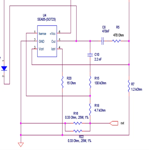
10W offline LED driver based on VIPER27 (DN0002)


Circuit Parameters and Component Values: Target Output Specifications: V_OUT = 15 V, I_OUT = 3 A (Test Target) Current Sense Resistor (R_SENSE / R16, R22): 18 mΩ

SEA05 Pin Configuration Components: R₁₈  = 3.75 kΩ, R₂₀ = 10 Ω,  R₅ = 10 kΩ, C₈ = 100 nF, C₁₀ = 1 nF, R₁₅ = 120 kΩ, R₇ = 10 kΩ,  R₆ = 51 kΩ

The Problem: According to the SEA05's internal 50 mV current sense threshold (V_SENSE), the converter should transition into Constant Current (CC) regulation at 2.77 A (calculated as 50 mV divided by 18 mΩ). Nevertheless, the converter operates exclusively in CV mode. Rather than stabilizing or limiting the voltage when load exceeds 2.77 A, the output voltage rises progressively under elevated load conditions.


Output Current (I_OUT) Output Voltage (V_OUT) Operating Mode
0 A 15.00 V CV
2 A 15.00 V CV
3 A 15.23 V CV (Should be CC)
4 A 15.30 V CV (Should be CC)


Inquiry: What is preventing the current loop from assuming control of the optocoupler node, and what accounts for the substantial increase in V_OUT under high-load operating conditions?

1 reply

Peter BENSCH
ST Technical Moderator
September 30, 2026

The most likely issue is that the SEA05 current loop is not actually able to dominate the optocoupler node. Please check the shunt polarity, Kelvin grounding of SEA05 GND, and whether the current loop can sink enough optocoupler LED current against the CV loop.

The rising VOUT​​ at high load usually indicates the primary-side loop is hitting a limit before true CC regulation takes over, so the supply is entering a boundary condition rather than proper current limiting.

  • Kelvin GND: The datasheet emphasizes that GND should be placed very close to the converter output terminal. If the SEA05 GND is raised by the load current as well, the reference level shifts, and the current measurement or the control comparison becomes inaccurate or ineffective.
  • CC vs CV: The two opamps are internally OR-gated. If the CV branch is already pulling the optocoupler so hard that the current branch cannot counteract it with its transconductance current, the converter remains in CV. This is especially critical when the primary side is designed such that the optocoupler has hardly any margin left for CC regulation.
  • Voltage rise from 15V to 15.23V or 15.30V at 3A to 4A: a strong indication that the primary side is going into some kind of current-limiting state before the secondary CC loop takes over: under load, the converter can no longer deliver enough energy per switching period, the optocoupler signal is determined not by CC but by the primary regulation, the control loop loses the clean CV/CC handover, and as a result the output voltage can rise instead of clamping precisely 50 mV above Rsense.

Please check:

  • What resistance does the shunt have: 2 x 0.33 ohm or 18 mOhm?
  • Is Ictrl connected to the negative shunt side and Isense to the positive shunt side?
  • As mentioned, the Kelvin connection at the output ground
  • Whether the CC branch takes effect when the CV feedback is artificially relieved
  • Whether, in the event of overcurrent, additional LED drive via OUT occurs
  • The primary-side limits on the UCC28C50: current limit, max duty cycle, COMP level, start/burst behaviour

The last point is especially important, because if the primary side limits earlier, the secondary CC loop can no longer counteract it.

Regards
/Peter

In order to give better visibility on the answered topics, please click on Accept as Solution on the reply which solved your issue or answered your question.