
Visitor
September 16, 2026
Question

L6983 output is the same as the supply voltage

  • September 16, 2026
  • 5 replies
  • 8 views

Hi,


I have been trying to implement the L6983 in my design for about 4 month now and still don’t get the desired output. After checking the Fsw pin, it seems I don’t get any clock output, do you have any idea what would be the cause of this issue ? Here is m design.
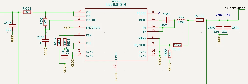
The 0Ohm strips are only for a backup power supply. 

The Fsw output is flat on GND at the oscilloscope.

The SW output before the inductor is at my supply voltage of 28V with small disconnects resulting in a flat 28V after the inductor.

The input is 28V and it should output 5.2V

The switching method should be 500kHz without dithering

Vs is delivered by a L6981 power supply + L39200 LDO at 3V3.


This issue is present on several iterations of this design even though we made sure to reference the ST eDesign Suite for our choices.

5 replies

AScha.3
Super User
September 16, 2026

Hi,

why use this old thing then ?

Try a new one : 

DCP3603BCMR , 3A , 36V in max. , see:

or from Ti


If you feel a post has answered your question, please click on " Best Answer ".
CharlesTPAuthor
Visitor
September 16, 2026

Hi,

As a European manufacturer, I am trying to limit my component choices to other European manufacturers which discards TI for most of my design choices unless the features are truly unique.


Also, this board is intended to go in an enclosed product that is very sensitive to its own EMI and dithering is not necessarily the best choice when you can filter them. So I wanted a product that would allow me to disable the dithering feature.

AScha.3
Super User
September 16, 2026

Hi,

that's what i also prefer , so DCP3603BCMR or ..BNMR could be your choice.

I will try it next time - its new.

+

+

>resulting in a flat 28V after the inductor.

This is  a killer - an absolute no-go (for me) ! 

OUT = IN indicates the chip is dead, or shorted; the worst case , when using a buck regulator.

> This issue is present on several iterations of this design

So i would never use this chip again or bother around with it. But … ymmv.

If you feel a post has answered your question, please click on " Best Answer ".
Associate II
September 16, 2026

Please check the recommended schematics and Input, Output capacitor with inductor may need to be selected based on datasheet recommendation. Not sure your schematics is right or not...

CharlesTPAuthor
Visitor
September 16, 2026

After a first failed attempt, it was decided to heavily base the design on ST eDesign Suite. All the values you see on the schematic are the one used on the actual board.