

Associate II
July 27, 2026
Question

Facing issue with the part TS4436 while using it as comparator application

  • July 27, 2026
  • 9 replies
  • 50 views

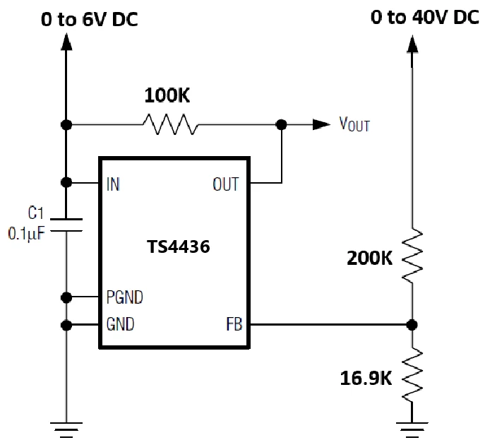
We have recently designed and implemented a PCB with TS4436 IC. And we are using this IC as a comparator in our application.

While testing, we have observed that the IC taking near 40mA as supply current during OUT enable time (for FB input > 0.6V). But as per datasheet it won't take more than 4mA.


We request you to go through the issue and share the resolution asap. 


Sharing our application schematic for reference.


9 replies

Peter BENSCH
ST Technical Moderator
July 27, 2026

In your schematics, the pin labels do not match those in the TS4436 datasheet. Are you sure you really mean the TS4436?

If pin 3 in the datasheet is the pin you have labelled IN, then your observation is correct, because you would then be short-circuiting your 6V supply with the internal output transistor.

Speaking of voltage: the TS4436 is not suitable for operating at a voltage of less than about 1.7V (at IN in your case), because it is not a conventional comparator, but a shunt reference for use in the feedback loop of switch-mode regulators

Speaking of the datasheet: there is nowhere any mention of a supply current of a maximum of 4mA; the specified maximum is 250µA.

Regards
/Peter

In order to give better visibility on the answered topics, please click on Accept as Solution on the reply which solved your issue or answered your question.
Mallik18Author
Associate II
July 27, 2026

Sharing Pin names updated schematic for reference.


Peter BENSCH
ST Technical Moderator
July 28, 2026

Just to make sure it really is the TS4436: does it have the marking L21 or L22?
If that is the case, and your schematic reflects reality, the supply current must remain well below 300µA, as there is an internal current source on the VCC pin that guarantees this value - provided the device has not been damaged.

Speaking of damaged: what are the test parameters for your board, specifically the voltage on VCC?

Regards
/Peter

In order to give better visibility on the answered topics, please click on Accept as Solution on the reply which solved your issue or answered your question.
Mallik18Author
Associate II
July 28, 2026

Verified the marking on the IC as L21.

We are experiencing high current issue when >0.6V given at REF pin.

Observing expected functionality as follows

When REF < 0.6V; SINK is floating state, voltage appeared according to pull up connected source.

When REF > 0.6V; SINK is 0V.


Peter BENSCH
ST Technical Moderator
July 28, 2026

Thank you for the information, but my last question is still open: what are the test parameters for your board, specifically the voltage on VCC while measuring the high current?

In order to give better visibility on the answered topics, please click on Accept as Solution on the reply which solved your issue or answered your question.
